background image


Scan mode function extension for ASCII readers 


3.2 Communication and parameter assignment 

ASCII protocol for RF200 
Operating Manual, 11/2016, C79000-G8976-C329-04 

25


The reader is in scan mode as soon as the message frame has been successfully 

transmitted. 

3.2


Communication and parameter assignment 

In the scan mode, data are transferred automatically to the host via the serial interface when 

the reader is switched on. The type of data acquisition and transmission is preset in the 

reader using parameters. 
For commissioning, it is also possible to communicate with the reader during operation. For 

this, the host transmits a frame via the serial interface that is processed and acknowledged 

in the reader. 
The following functions are available for the commissioning: 


Change parameters 


Read status (incl. parameters) 

The information about the FW/HW version is appended to the parameters when reading. 


Enable test mode 


NOTICE 
Loss of transponder information in host-reader communication during operation 
When you start the communication between host and reader during commissioning, make 

sure that there are no transponders in the antenna field at that time. In this way, the 

reader's acknowledgement of a frame from the host can be directly recognized as such. 

Otherwise, the reply data of the reader may include transponder data along with the 

acknowledgement. 


NOTICE 
Documenting parameter changes 
A change in the communication-relevant parameters “baud rate” and “parity” must be well 

documented, because with unknown interface parameter assignment, the reader cannot be 

addressed and can also no longer receive user data. 
If the interface setting in the reader is no longer known, the host must search for the setting: 

using the “read status” frame, for example. It may be necessary to test all combinations 

with the “baud rate” and “parity” parameters until a frame is acknowledged as valid. 


NOTICE 
Changes in scan mode are retentive 
Not that changes made in scan mode can be saved retentively. If parameters are saved 

retentively in the reader, the reader will still retain these stored values after changing 

modes. 


Summary of Contents for SIMATIC RF200

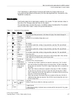
Page 1: ..._________ ___________________ ___________________ SIMATIC Ident RFID systems ASCII protocol for RF200 Operating Manual 11 2016 C79000 G8976 C329 04 Introduction 1 Command and message frames 2 Scan mode function extension for ASCII readers 3 Reader 4 Transponder 5 Appendix A Service Support B ...

Page 2: ...e operated only by personnel qualified for the specific task in accordance with the relevant documentation in particular its warning notices and safety instructions Qualified personnel are those who based on their training and experience are capable of identifying risks and avoiding potential hazards when working with these products systems Proper use of Siemens products Note the following WARNING...

Page 3: ...de 3 command 15 2 7 SET ANT acknowledgement 17 2 8 SET RS232 command 17 2 9 RESET command 18 2 10 ANW MELD message 19 2 11 Error messages 21 3 Scan mode function extension for ASCII readers 23 3 1 Retentively enabling disabling scan mode 24 3 2 Communication and parameter assignment 25 3 3 Communication in scan mode 26 3 3 1 Change parameters frame 29 3 3 2 Read status frame 30 3 3 3 Enable test m...

Page 4: ...of contents ASCII protocol for RF200 4 Operating Manual 11 2016 C79000 G8976 C329 04 A Appendix 41 A 1 PC driver LAUF 3964R 41 A 2 Connecting cables 41 A 3 Wide range power supply unit 43 B Service Support 45 ...

Page 5: ...along with their memory configuration Target group This manual is intended for application developers who want to operate the RFID system RF200 on controllers or host systems with the RS 232 serial interface Registered trademarks SIMATIC SIMATIC NET SIMATIC RF and MOBY are registered trademarks of Siemens AG Additional information You will find more information in RF200 system manual http support ...

Page 6: ...s control character configuration on the reader is unnecessary A frame is uniquely identified by the control characters for the start and end the procedure has no other reliability mechanisms or length information The amount of data to be transferred is restricted by the monitoring time and by the length byte in the frame Receipt of the frame is monitored with a monitoring time of 300 ms If the ho...

Page 7: ...the interface parameters set in the driver and on the reader match If you cannot use the reader with the default settings follow the steps below to change settings of the serial interface 1 Connect the reader to a PC 2 Send the interface frame SET RS232 using a standard PC tool e g HyperTerminal The reader can then be deployed in the target environment Note Run SET RS232 before the first RESET To ...

Page 8: ... of commands was dispensed with in the ASCII protocol A command is always followed by the corresponding acknowledgement that must arrive before new commands can be sent This means that interface communication remains simple Only one command can ever be active on the reader This rule does not apply to the following commands The RESET command can be sent at any time to re initialize the reader The S...

Page 9: ...this in the section ANW MELD message Page 19 With the passive presence check without presence the presence of a transponder is also indicated by the yellow reader LED lighting up however no frame is sent to the host system In this mode presence can be queried on the reader by the host with the SLG STATUS command mode 0 Table 2 1 The following commands are supported Command Description READ Read tr...

Page 10: ... 0x30 Byte 5 0x30 Byte 6 User data address high byte high nibble Read UID 46 46 46 30 hex The max permitted address corre sponds to the memory size 1 byte Infineon 0x30 0x33 0x44 0x46 NXP 0x30 0x30 0x36 0x46 Fujitsu 0x30 0x37 0x43 0x46 TI ST 0x30 0x30 0x46 0x46 Byte 7 high byte low nibble Byte 8 low byte high nibble Byte 9 low byte low nibble Byte 10 User data length high nibble Length of user dat...

Page 11: ...ription Byte 0 Frame length high nibble Net data length of the frame 1 byte depending on data length Byte 1 low nibble Byte 2 Command 0x30 Byte 3 0x31 Byte 4 Status 0x30 Byte 5 0x30 Byte 6 User data address 0x30 The max permitted address corre sponds to the memory size 1 byte Infineon 0x30 0x33 0x44 0x46 NXP 0x30 0x30 0x36 0x46 Fujitsu 0x30 0x37 0x43 0x46 TI ST 0x30 0x30 0x46 0x46 Byte 7 high byte...

Page 12: ...ode 0 command Address Designation Value Description Byte 0 Frame length 0x30 Net data length of the frame 1 byte Byte 1 0x36 Byte 2 Command 0x30 Byte 3 0x34 Byte 4 Status 0x30 Byte 5 0x30 Byte 6 Mode 0x30 Mode 0 Byte 7 0x30 Byte 8 Reserve 0x30 Byte 9 0x30 Byte 10 Reserve 0x30 Byte 11 0x30 Byte 12 Reserve 0x30 Byte 13 0x30 Table 2 7 SLG STATUS mode 0 acknowledgment Address Designation Value Descrip...

Page 13: ...escription Byte 0 Frame length 0x30 Net data length of the frame 1 byte Byte 1 0x36 Byte 2 Command 0x30 Byte 3 0x34 Byte 4 Status 0x30 Byte 5 0x30 Byte 6 Mode 0x30 Mode 1 Byte 7 0x31 Byte 8 Reserve 0x30 Byte 9 0x30 Byte 10 Reserve 0x30 Byte 11 0x30 Byte 12 Reserve 0x30 Byte 13 0x30 Table 2 9 SLG STATUS mode 1 acknowledgment Address Designation Value Description Byte 0 Frame length 0x31 Net data le...

Page 14: ...le Firmware version format xx yy Byte 21 xx low nibble Byte 22 yy high nibble Byte 23 yy low nibble Byte 24 TR 0x33 Driver variant LAUF Byte 25 0x33 Byte 26 TR V xx high nibble Version of the driver format xx yy Byte 27 xx low nibble Byte 28 yy high nibble Byte 29 yy low nibble Byte 30 SS 0x30 0x31 RS 422 interface 0x32 RS 232 interface Byte 31 0x31 0x32 Byte 32 Baud rate 0x30 0x31 19 2 kBd 0x33 5...

Page 15: ...with presence 0x34 presence with command Byte 55 0x30 0x31 0x34 2 6 MDS STATUS mode 3 command Table 2 10 MDS STATUS mode 3 command Address Designation Value Description Byte 0 Frame length 0x30 Net data length of the frame 1 byte Byte 1 0x35 Byte 2 Command 0x30 Byte 3 0x42 Byte 4 Status 0x30 Byte 5 0x30 Byte 6 Mode 0x30 Mode 3 Byte 7 0x33 Byte 8 Reserve 0x30 Byte 9 0x30 Byte 10 Reserve 0x30 Byte 1...

Page 16: ...e 20 byte 1 high nibble Byte 21 byte 1 low nibble Byte 22 byte 0 high nibble Byte 23 byte 0 low nibble Byte 24 Transponder type 0x30 transponders recognized in anten na field Byte 25 0xXX XX 33 Infineon XX 34 Fujitsu XX 35 Philips XX 36 TI Tag it XX 37 ST XX 31 other Byte 26 Version high nibble ICReference from Get System Information or ChipType from UID Infineon Byte 27 low nibble Byte 28 Variabl...

Page 17: ...0x31 antenna off Byte 7 0x31 0x32 Table 2 13 SET ANT acknowledgement Address Designation Value Description Byte 0 Frame length 0x30 Net data length of the frame 1 byte Byte 1 0x32 Byte 2 Command 0x30 Byte 3 0x41 Byte 4 Status high nibble Error code error_Moby Byte 5 low nibble 2 8 SET RS232 command Table 2 14 SET RS232 command Address Designation Value Description Byte 0 Frame length 0x30 Net data...

Page 18: ...1 0x32 Byte 2 Command 0x42 Byte 3 0x42 Byte 4 Status high nibble Error code error_Moby Byte 5 low nibble 2 9 RESET command Table 2 16 RESET command Address Designation Value Description Byte 0 Frame length 0x30 Net data length of the frame 1 byte Byte 1 0x41 Byte 2 Command 0x30 Byte 3 0x30 Byte 4 Status 0x30 Byte 5 0x30 Byte 6 ScanningTime 0x30 Reserved Byte 7 0x30 Byte 8 Param 0x30 Operating mode...

Page 19: ...e 2 17 RESET acknowledgment Address Designation Value Description Byte 0 Frame length 0x30 Net data length of the frame 1 byte Byte 1 0x35 Byte 2 Command 0x30 Byte 3 0x30 Byte 4 Status high nibble Error code error_Moby Byte 5 low nibble Byte 6 Firmware version xx high nibble Firmware version Format xx yy Byte 7 xx low nibble Byte 8 yy high nibble Byte 9 yy low nibble Bytes 10 11 Reserved 0x30 2 10...

Page 20: ...With the active presence check if there is a change in the presence status the reader sends a frame with the number of transponders in the antenna field If a transponder leaves the field at the same time as another transponder enters the field two ANW MELD messages are sent Note Reachability of the host The presence message is asynchronous i e without a request from the host This means that the ho...

Page 21: ...r Function not allowed 06 0x06 Air interface faulty 12 0x0C The transponder memory cannot be written possible cause Hardware fault memory faulty Write protected transponder 13 0x0D Error in the specified memory address access attempted to non existent or non accessible memory areas 19 0x13 Buffer overflow Insufficient buffer available on the reader for saving the command 20 0x14 Serious system fau...

Page 22: ...for RF200 22 Operating Manual 11 2016 C79000 G8976 C329 04 Note Manufacturer dependent error messages With transponders with a blocked protected memory area different error messages e g error 0x01 0x0C can occur depending on the manufacturer type NXP Infineon etc ...

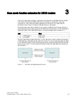
Page 23: ...mode the RF200 ASCII readers operate in exactly the same way autonomously as an RF300 scan mode reader It is not necessary to restart the reader The reader LED shows you which operating mode the reader is in LED Mode Flashing green ASCII mode Lit up green Scan mode Using the parameter assignment frames you can also store all other parameters retentively in the reader e g transmission rate data to ...

Page 24: ...ode as soon as the command has been successfully acknowledged Disabling scan mode enabling ASCII mode To disable scan mode you must set the Scan mode parameter to the value 0x02 using the Change parameters frame Table 3 2 Structure of the Change parameters frame binary Command parameter Frame parameter Byte 1 Byte 2 Byte 3 Byte 1 Byte 2 Byte 3 Byte 4 Command Status Count Tag type Modulation Subcar...

Page 25: ...tion in host reader communication during operation When you start the communication between host and reader during commissioning make sure that there are no transponders in the antenna field at that time In this way the reader s acknowledgement of a frame from the host can be directly recognized as such Otherwise the reply data of the reader may include transponder data along with the acknowledgem...

Page 26: ...eader transmits the acknowledgement after it has finished performing the command Conditions for frame transmission The following conditions apply for frame transmission The BCC checksum is calculated by simple XORing of all bytes If an interface parameter is changed baud rate parity the acknowledgement is sent with the old setting The new setting then takes effect scan data next frame After connec...

Page 27: ...er defined 1 double 4 0 high Data rate Air interface optimization setting is only possible by selecting ISO user defined 1 low 5 0 Single tag Operating mode Only single tag setting is possible If there are multiple transponders in the antenna field these are not identified and cannot be processed 1 reserved 6 0 Continuous Read Scan mode Selection of scan mode sequence Continuous read Read operatio...

Page 28: ...h Specification of amount of user data that should be read user data setting 1 1024 1 1024 18 0 ascii Data format Setting for data transfer type Bytes are transferred as binary bytes or are converted into two ASCII characters This parameter does not apply to the separator or end of text character binary This parameter does not apply to frame traffic either 1 binary 19 0 CR LF Separator Setting for...

Page 29: ...e parameters can be stored in the reader either retentively or non retentively In a retentive parameter assignment the transmitted data are still available after the reader is powered up again In non retentive parameter assignment the data are only changed for current operation The previous parameters are used the next time the reader is powered up After the parameters are accepted and the acknowl...

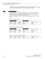
Page 30: ...an identify individual readers by the version information This information is specified at factory and cannot be changed After the acknowledgement is sent the reader switches automatically back to read data mode Table 3 13 Read status frame Command parameter Frame parameter Byte 1 Byte 2 Byte 3 Byte 1 Byte 21 BCC Command Status Count Para Para 0x02 0x00 0x15 0x00 0x00 Table 3 14 Read status frame ...

Page 31: ...22 contains the contents of yy 23 24 Indicates the hardware version in ASCII format 25 Indicates the FPGA version 3 3 3 Enable test mode frame This frame helps you when commissioning a reader Test mode is enabled in the reader immediately after the acknowledgement is transmitted You can disable test mode by turning the reader off or transmitting a new parameter record In test mode the reader conti...

Page 32: ...that the parameters have not been accepted The following table lists all possible error codes Table 3 19 Error messages Error code Description 0x01 Command is unknown in first byte of frame 0x02 Status is unknown in second byte of frame 0x03 A parameter setting is faulty 0x04 BCC is faulty in last byte of frame 0x05 Data could not be stored retentively FEPROM are not identified 0x06 Data could not...

Page 33: ...us indicator on the reader Color Description Operating voltage present reader not initialized or antenna turned off Operating voltage present reader initialized and antenna turned on 1 Transponder present Command execution active when operating without presence Error has occurred the type of flashing corresponds to the error code in the table in the section Error messages The optical error display...

Page 34: ...Reader 4 2 LED status indicator ASCII protocol for RF200 34 Operating Manual 11 2016 C79000 G8976 C329 04 ...

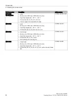
Page 35: ...memory Operating temperature 25 C 180 C Dimensions Ø x H 27 0 2 x 4 0 2 mm 6GT2600 0AC10 MDS D126 IP68 Memory size 112 bytes of EEPROM user memory Operating temperature 25 C 85 C Dimensions Ø x H 50 x 3 6 mm Round design with mounting hole 6GT2600 0AE00 MDS D127 IP68 IPx9K Memory size 112 bytes of EEPROM user memory Operating temperature 25 C 125 C Dimensions Ø x H M6 x 5 0 2 mm 6GT2600 0AF00 MDS ...

Page 36: ...x 55 mm Smartlabel PET small design 6GT2600 1AA00 0AX0 MDS D324 IP67 IPx9K Memory size 992 bytes of EEPROM user memory Operating temperature 25 C 125 C Dimensions Ø x H 27 0 2 x 4 0 2 mm 6GT2600 3AC00 MDS D339 IP68 IPx9K Memory size 992 bytes of EEPROM user memory Operating temperature 25 C 220 C Dimensions Ø x H 85 0 5 x 15 1 0 mm 6GT2600 3AA10 MDS D400 IP67 Memory size 2000 bytes of FRAM user me...

Page 37: ...GT2600 4AG00 MDS D426 IP68 Memory size 2000 bytes of FRAM user memory Operating temperature 25 C 85 C Dimensions Ø x H 50 x 3 6 mm Round design with mounting hole 6GT2600 4AH00 MDS D428 IP68 IPx9K Memory size 2000 bytes of FRAM user memory Operating temperature 25 C 85 C Dimensions Ø x H 18 1 x 20 1 mm without thread thread M8 6GT2600 4AK00 0AX0 MDS D460 IP67 IPx9K Memory size 2000 bytes of FRAM u...

Page 38: ...nto metal flush mounted 6GT2600 5AF00 0AX0 MDS D524 IP67 Memory size 8192 bytes of FRAM user memory Operating temperature 25 C 85 C Dimensions Ø x H 27 0 2 x 4 0 2 mm 6GT2600 5AC00 MDS D526 IP67 IPx9K Memory size 8192 bytes of FRAM user memory Operating temperature 25 C 85 C Dimensions Ø x H 50 x 3 6 mm Round design with mounting hole 6GT2600 4AH00 MDS D528 IP68 IPx9K Memory size 8192 bytes of FRA...

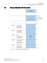
Page 39: ... 2 Memory configuration of the transponders ASCII protocol for RF200 Operating Manual 11 2016 C79000 G8976 C329 04 39 5 2 Memory configuration of the transponders Figure 5 1 Memory configuration of the transponders ...

Page 40: ... 8 byte long unique serial number UID read only This UID is transferred as an 8 byte value by a read command to address FFF0 with a length of 8 Note Special feature of the NXP transponder The NXP chip has the quirk of NOT responding to bad commands Here there is no error message and the command behaves as if the transponder was not in the antenna field Note Special feature of the Fujitsu transpond...

Page 41: ...ns between a PC as host and the reader You will find the driver on the DVD RFID Systems Software Documentation 6GT2080 2AA20 or on the Internet on the Support homepage http www siemens com automation service support A 2 Connecting cables With 4 pin power supply connector The connecting cable 6GT2891 4KH50 is 5 m long Special feature of the cable additional branch for the power supply Figure A 1 Co...

Page 42: ... cables ASCII protocol for RF200 42 Operating Manual 11 2016 C79000 G8976 C329 04 With open ends for the power supply Figure A 2 Connecting cable between PC and RF240R RF260R RF290R RS 232 with open ends for the power supply ...

Page 43: ...ion has been UL certified for the US and Canada Wide range power supply unit for SIMATIC RF systems Characteristics Application Supplying power to Siemens Ident devices Degree of protection IP67 Design features Mechanically and electrically rug ged design Short circuit and no load stability Suitable for frame mounting Structure Network connector PE DC output 1 DC output 2 Table A 1 Ordering data f...

Page 44: ...24 V connecting cable for SIMATIC RF620R RF630R RF640R RF670R 5 m 6GT2891 0NH50 24 V connecting cable for SIMATIC RF650R RF680R RF685R 5 m 6GT2891 0PH50 24 V connecting cable for readers of the SIMATIC product family MOBY D 5 m 6GT2491 1HH50 24 V connecting cable for SIMATIC RF200 RF300 with RS 232 5 m 6GT2891 4KH50 24 V connecting cable for SIMATIC RF200 RF300 with open ends at the power supply u...

Page 45: ...sioning through to maintenance and modernization You will find contact data on the Internet at the following address Link 3 http w3 siemens com aspa_app RFID homepage For general information about our identification systems visit RFID homepage http w3 siemens com mcms identification systems Online catalog and ordering system The online catalog and the online ordering system can also be found on th...

Page 46: ...Service Support ASCII protocol for RF200 46 Operating Manual 11 2016 C79000 G8976 C329 04 ...

Reviews: