RF600 system planning
4.2 Antenna configurations
RF600
4-2
System Manual, 09/2005 Edition, J31069 D0171-U001-A0-7618,
4.2
Antenna configurations
4.2.1
Antenna configuration example
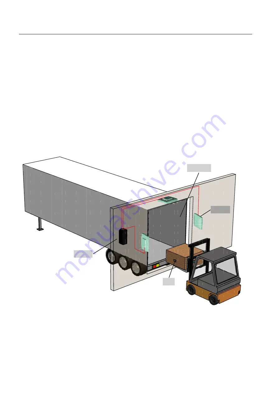
The following diagram shows an example of a portal configuration. The antenna are
positioned at the height at which the tags are expected which are to be identified. The
maximum width of the portal that is recommended for reliable operation is 4 m.
The diagram shows a configuration with two antennas. Up to four antennas can be used
depending on the local conditions.
5HDGHU
$QWHQQH
7DJ
/DGHUDPSH
Figure 4-1
Typical gate configuration


