RF600 system planning
4.6 Guidelines for electromagnetic compatibility (EMC)
RF600
4-30
System Manual, 09/2005 Edition, J31069 D0171-U001-A0-7618,
Cable tie
5HPRYHSDLQW
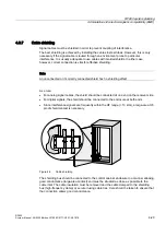
Figure 4-10 Connection of shielding bus
The shielding bus must be connected to the PE busbar.
If shielded cables have to be interrupted, the shield must be continued via the corresponding
connector housing. Only suitable connectors may be used for this purpose.
6KLHOGWXUQHGXSVLGHGRZQ
WKURXJKrDQG
FRQQHFWHGWRFRQQHFWRU
KRXVLQJ
5XEEHUVOHHYH
Figure 4-11 Interruption of shielded cables
If intermediate connectors, which do not have a suitable shield connection, are used, the
shield must be continued by fixing cable clamps at the point of interruption. This ensures a
large-area, HF-conducting contact.


