background image

6-5

Product Information Bulletin RI45 PII
C79000-Z7076-C814-02

6.6

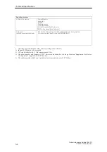
The Clock Time and/or the Date in Your PC Is Incorrect

Set the clock time and the date in the setup menu.

Press <F2> to call setup when booting the computer.

Note

The battery is dead if the clock time and the date are still incorrect after you
switch off your PC and switch it back on again. In this case, please contact
your technical support team (Chapter 7).

6.7

Rebooting Your Hard Drive (Data Deleted)

Windows NT

Note
Applies only to devices with pre-installed operating systems.

Follow the instructions given in the chapter on installation in the User’s
Guide Introducing Microsoft Windows NT.

To re-install the supplied drivers and the electronic documentation, use the
backup diskettes which you created.

Remedy

Error Diagnostics

Summary of Contents for SIMATIC RI45 PII Series

Page 1: ...Product Information Bulletin SIMATIC RI45 PII C79000 Z7076 C814 02 ...

Page 2: ...inthecatalogortechnicaldescription and only in connection with devices or components from other manufacturers which have been approved or recommended by Siemens Thisproductcanonlyfunctioncorrectlyandsafelyifitistransported storedandsetupcarefullyand correctly and operated and maintained as recommended SIMATICR SIMATIC NETR and SIMATIC HMIR are registered trademarks of SIEMENS AG The reproduction t...

Page 3: ... Cabinet or Rack RI45 PII 19 Operation 2 7 2 5 Drives 2 8 3 Setting Up and Operating the RI45 PII 3 1 3 1 Connecting the RI45 PII to the Power Supply 3 2 3 2 Connecting I O Devices 3 4 3 3 Keyboard 3 6 3 4 Starting Up Your PC for the First Time 3 7 3 5 Electronic Manual 3 8 3 6 Installing Adobe Acrobat 3 9 3 7 Backing Up Hard Disk Data on Diskettes 3 9 4 Expanding the RI45 PII 4 1 4 1 Opening the ...

Page 4: ...3 The Monitor Remains Dark 6 3 6 4 The Screen Display Does not Appear or Drifts 6 4 6 5 No Mouse Pointer Appears on the Screen 6 4 6 6 The Clock Time and or the Date in Your PC Is Incorrect 6 5 6 7 Rebooting Your Hard Drive Data Deleted 6 5 6 8 An Error Message Appears on the Screen 6 6 6 9 RI45 PII Self Test Prior to Booting 6 7 7 Service Representatives 7 1 7 1 Regional Repair Centers 7 3 Conten...

Page 5: ... must follow when you operate your PC and its components This device corresponds to the relevant safety measures according to IEC EN VDE UL and CSA If you have questions about the permissibility of the installation in the designated environment please contact our service representative Chapter 7 contains the service address locations Chapter Overview 1 ...

Page 6: ...safety tested power supply cable You may connect this device only to a grounding outlet with a grounding contact Make certain that the socket outlet on the device or the grounding contact for the building wiring system is freely accessible The mains switch does not separate the device from the power system To establish a complete power separation you must disconnect the power plug inlet connector ...

Page 7: ...sed your PC to find out which system expansion devices may safely be installed If you install or exchange system expansions and damage your PC the warranty becomes void The following sticker can be used to identify modules with ESD electrostatically sensitive devices If you handle modules with ESD it is essential that you adhere to the following guidelines S Before you work with modules with ESD y...

Page 8: ...963 D 92209 Amberg Germany Products not bearing the CE label fulfill the requirements and standards as specified in the section on Technical Specifications The installation guidelines and safety instructions specified in the documentation must be observed during startup and operation The requirements regarding noise immunity EN50082 2 1995 are met when you connect a peripheral switable for an indu...

Page 9: ...the USA and Canada The following labels indicate that the relevant approval is available for the device bearing the label Underwriters Laboratories UL to standard UL 1950 Underwriters Laboratories UL to Canadian standard C22 2 No 950 Underwriters Laboratories UL to standard UL 1950 Report E11 5352 and Underwriters Laboratories UL to standard UL 1950 Report E11 5352 and to Canadian standard C 22 2 ...

Page 10: ... expense Shielded Cables Shielded cables must be used with this equipment to maintain compliance with FCC regulations Modifications Changes or modifications not expressly approved by the manufacturer could void the user s authority to operate theequipment Conditions of Operations This device complies with Part 15 of the FCC Rules Operation is subject to the following two conditions 1 this device m...

Page 11: ...er describes how to install the RI45 PII and contains all the information you need to know about its most important components S Device models S Installing and transporting S Hardware components interfaces S Keyboard S Installing your PC in a 19 cabinet or rack RI45 PII 19 operation S Drives Chapter Overview 2 ...

Page 12: ...g rack it is equipped with a module retainer and an air filter This model is designed for office use it is equipped with a sound card and is also supplied with a keyboard and a mouse This model is designed for table top use it is only available as a PCS7 device Rack Desktop Tower PC RI45 PII PC RI45 PII PC RI45 PII Figure 2 1 Device Models of the RI45 PII Rack Tower Desktop Unpacking and Installin...

Page 13: ... unit The unit should be allowed to reach room temperature slowly before it is started up If condensation has formed the unit should be left for about 12 hours before being switched on Fill the serial number of your RI45 PII in the table below If your device has been stolen and repair work is required the repair and maintenance centers can only identify it by its serial number Serial number RI45 P...

Page 14: ... 9 2 1 Rack Tower 9 8 7 6 5 4 1 3 2 PC RI45 PII PC RI45 PII Power LED Hard disk access MPI DP port Power MPI DP RUN with SafeCard only TEMP with SafeCard only 1 LED displays 2 Reset button 3 Lock for drive cover access protection 4 CD ROM drive 5 Free slot 6 Diskette drive 7 On Off switch 8 Protective cover for disk drive 9 Ventilating slots Figure 2 2 Front of the RI45 PII Front Unpacking and Ins...

Page 15: ...2 9 On Off switch B B Supply voltage selector switch 1 14 1 5 9 11 6 7 8 10 12 B 4 3 13 14 1 Cooling fan 2 Strain relief device rack only 3 Microphone tower only 4 Loudspeaker tower only 5 Dummy plates covering expansion slots 6 COM2 7 COM1 8 MPI DP 9 VGA 10 LPT1 11 PS 2 mouse 12 PS 2 keyboard 13 Grounding studs 14 Supply voltage selector switch 15 Relay with SafeCard only 5 Figure 2 3 Rear Panel ...

Page 16: ... Connection for serial printer VGAInterface Connection for external monitor Loudspeaker RI45 PII Tower only Connection for external stereo loudspeaker Microphone RI45 PII Tower only Connection for microphone mono Relay output with SafeCard only Connection of a signaling unit to the SafeCard monitoring module Technicaldata Switching voltage DC max 60V Switching current DC max 1A Switching power DC ...

Page 17: ...77 38 10 448 438 482 18 31 19 02 17 64 1 5 4 61 3 98 0 39 17 24 18 98 All dimensions in mm All dimensions in inches Figure 2 4 SIMATIC PC RI45 PII Installation Dimensions Warning Avoid extreme ambient conditions as far as possible Protect your SIMATIC PC from dust moisture and heat Refer to the System Unit section in the Technical Description Mount the device as safely as possible to prevent any d...

Page 18: ...r improved ventilation and protection against dirt the cover should be closed during operation You can store programs and data on diskettes with the disk drive and load them from diskettes into the RI45 PII The RI45 PII is equipped with the following drives as standard You can use the following diskettes Double SidedHigh Density Diskette Double SidedDouble DensityDiskette 3 5 in 3 5 in 1 44 Mbytes...

Page 19: ...OM drive allows you to load programs and data from CDs The CD ROM drive is connected to the secondary IDE interface 1 2 3 4 5 6 This jack is used to connect a set of headphones Please use headphones with a stereo mini jack plug This control is used to adjust the headphone volume This control has no effect on the left and right audio outputs from the LINE OUT connector on the back of the unit This ...

Page 20: ...1 Turn off the power to the CD ROM reader switch off your device if neces sary 2 Insert a steel rod or a stiff paper clip with a maximum diameter of 1 3 mm and a minimum length of 55 mm into the emergency eject hole at the front of the drive and push lightly The CD tray is ejected by about 10 mm Pull it all the way open by hand and lift the disk out carefully at least 55 mm in length By pushing th...

Page 21: ...s chapter describes all the actions that you must perform in order to set up your workplace successfully S Connecting the RI45 PII to the power supply S Connecting I O devices S Information about the keyboard S Using the electronic documentation S Backing up hard disk data on diskettes Chapter Overview 3 ...

Page 22: ...ystem selector switch does not correspond with your local voltage you must move the supply voltage selector so that the marker points to the required supply voltage To do this use a small flat screwdriver to lever out the part with the voltages printed on it and replace it in the appropriate position B Voltagemarking On Off switch Supply voltage selector Appliance socket outlet Appliance socket in...

Page 23: ...240 V within the USA Use a UL listed CSA labeled cord set consisting of a min 18 AWG Type SVT or SJT three conductor flexible cord max 4 5 m 15 feet in length and a tandem blade grounding type attachment plug rated 15 A 250 V For operation with 230 V outside of USA Use a cord set consisting of a min 18 AWG cord and grounding type attachment plug rated 15A 250 V The cord set should have the appropr...

Page 24: ...tch on your device again You can connect both a PS 2 and a serial mouse to the RI45 PII The corresponding mouse driver must be loaded before operation Note A PS 2 mouse and a serial mouse cannot be operated at the same time B 3 Tower B Rack 1 Port for PS 2 keyboard 2 Port for PS 2 mouse 3 COM2 port for serial mouse 2 1 1 2 3 Figure 3 2 Connections for Keyboard PS 2 Mouse and Serial Mouse Connectin...

Page 25: ... Plug the monitor cable into the VGA socket 3 Plug the other end of the monitor cable into the monitor For technical specifications on the graphics interface please refer to the Product Information Bulletin Caution Danger of damaging the monitor If you want to set higher frequencies and resolutions first make sure that the monitor you are using is suitable for a higher frequency and resolution If ...

Page 26: ...qualized To do this briefly touch an earthed object ESD Guidelines Only use the original connecting cables 3 3 Keyboard The keyboard has an international German labeling system International Shift Unshift German ß Togetherwith the ALT Gr key Figure 3 3 The Keyboard Labeling System In the current versions of Windows 98 and Windows NT the German international character set contains the euro symbol w...

Page 27: ... Monitoring time run out Temp LED green red Temperature in the device is normal only with the SafeCard option Internaltemperatureiscritical When you switch on your PC it automatically executes a self test that tests all of the important PC components for reliability performance The diagnostics display provides you with information about the individual test steps In case of an error this display pr...

Page 28: ...MANI PDF Product Information Bulletin Italian c DOCU U_MANS PDF Product Information Bulletin Spanish The Technical Description is located in the directory DOCU c DOCU T_DESD PDF Techn Description German c DOCU T_DESE PDF Techn Description English You need the ADOBE Acrobat Reader to read and print out the Product Information Bulletin and the Technical Description The ADOBE Acrobat Reader is a soft...

Page 29: ... or the mouse to switch between windows Use the cursor keys on the keyboard or use the mouse to move the cursor between windows Important your selection is not chosen until the line is displayed inversely that is white lettering on a dark background 2 Open the file you want to read The files are located in the c docu directory 3 Use the FILE menu to print out the opened file First choose PRINTER S...

Page 30: ...3 10 ProductInformation Bulletin RI45 PII C79000 Z7076 C814 02 Setting Up and Operating the RI45 PII ...

Page 31: ...00 Z7076 C814 02 Expanding the RI45 PII This chapter describes how to expand your device S Opening the unit S Components visible after opening the unit S Installing a memory expansion card S Changing the backup battery S Options Chapter Overview 4 ...

Page 32: ...uit boards are extremely sensitive to electrostatic discharge Certain precautionary measures are therefore necessary when handling such components These measures are explained in the guidelines for handling electrostatically sensitive devices at the end of this manual ESD Guidelines All technical specifications and licences apply only to expansion functions approved by SIEMENS No liability can be ...

Page 33: ...ging in or removing any modules or components S Only touch components and modules on their edges Above all do not touch the connecting pins and printed conductors S Never operate the RI45 PII with the cover open For undoing combi TORX normal or Phillips screws use the appropriate screwdriver Open your device as follows 1 Switch off the device pull out the power supply connector and remove all conn...

Page 34: ...ible 5 6 7 9 10 1 8 PCI graphics card 9 Sound interface card for RI45 PII Tower only 10 Hard disk drive support 11 Power supply 12 Backup battery 13 Disk drive support 1 Floppy disk drive 2 PII CPU with heat sink 3 VR submodule 4 DIMM memory max 3 5 Fan 6 Mother board 7 Bus board with expansion slots 8 13 11 12 3 2 4 Figure 4 2 The RI45 PII Opened up View Expanding the RI45 PII ...

Page 35: ...e I Os are controlled and managed ÏÏÏÏ ÏÏÏÏ ÏÏÏÏ ÏÏÏÏ ÏÏÏÏ ÏÏÏÏ ÏÏÏÏ ÏÏÏÏ ÏÏÏÏ ÏÏÏÏ ÏÏÏÏ ÏÏÏÏ Processor plugged on X12 X11 X10 X800 X9 X7 X12 X1 X100 X27 X701 X120 X4 X3 X40 X80 X90 X24 X19 X20 X21 X26 X30 DIMM DIMM DIMM 4 3 2 1 S3 S2 1 2 3 4 X6 X160 1 2 X502 1 X501 1 1 2 1 2 X61 X63 X60 2 1 X17 X18 X414 2 1 Figure 4 3 Mother Board Mother Board Expanding the RI45 PII ...

Page 36: ...tery Plug for lithium battery X26 Fan Fan connection 12 V X30 Fan Fan connection 12 V X40 USB Internal Universal Serial Bus connection for USB sound card X50 Floppy disk Floppy disk interface X60 Microphone Internal microphone connection for USB sound card for RI45 PII Tower only X61 Loudspeaker Internal loudpseaker connection for USB sound card for RI45 PII Tower only X63 CD ROM line output Inter...

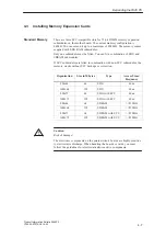
Page 37: ...modules are fitted in combination with non ECC submodules the memory works without ECC backups or correction Organisation Size in Mbytes Type Access Time Frequency 8Mx64 64 EDO 60ns 16Mx64 128 EDO 60ns 8Mx72 64 EDO with ECC 60ns 16Mx72 128 EDO with ECC 60ns 8Mx64 64 SDRAM 83MHz 16Mx64 128 SDRAM 83MHz 8Mx72 64 SDRAM with ECC 83MHz 16Mx72 128 SDRAM with ECC 83MHz Caution Risk of damage The electroni...

Page 38: ...y releasing the clips 6 Close the unit Caution Risk of damage The cards must sit firmly in their slots otherwise they might be damaged Plug the cards into their slots vertically before locking them in position Caution Risk of short circuit Incorrect insertion of the DIMM card may result in destruction of the card and the mother board Ensure that the contacts of the DIMM card and the receptacle are...

Page 39: ...Fix the new battery to the mother board with a cable binder 5 Close the unit Warning Risk of severe personal injury or property damage danger of release of harmful substances There may be a danger of explosion if the battery is not handled properly Incorrect disposal of used batteries can cause the release of harmful substances Do not throw a new or discharged battery into an open fire Do not sold...

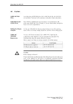
Page 40: ...can add to the functionality of your RI45 PII by expanding the configuration of the hardware to fit your individual requirements The following table shows the options offered by Siemens Please contact your Siemens sales representative for further options Option Order Number 64 Mbytes memory expansion 6ES7791 0FR00 0XA0 128 Mbytes memory expansion 6ES7791 0FS00 0XA0 Caution Risk of damage to the un...

Page 41: ...5 1 ProductInformation Bulletin RI45 PII C79000 Z7076 C814 02 Technical Specifications In this chapter you will find the technical specifications Chapter Overview 5 ...

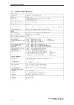
Page 42: ...cess lines measuring lines signal lines 1 kV to IEC 1000 4 4 burst length 3m 1 kV to IEC 1000 4 5 surge symm length 20m 2 kV to IEC 1000 4 5 surge unsymm length 20m Noise immunity to discharges of static electricity 6kV contact discharge to IEC 1000 4 2 8kV air discharge to IEC 1000 4 2 Noise immunity to high frequencynoise 10 V 10KHz 80 MHz 80 AM to IEC 1000 4 6 10 V m 80 1000 MHz 80 AM to IEC 10...

Page 43: ...be expanded to 8 MB Resolutions frequencies colors up to 1600x1200 with 80 Hz 65K colors Interfaces COM1 Serial port 1 V24 25 pin sub D socket COM2 Serial port 2 V24 9 pin sub D connector standard LPT1 Parallelport Connection for printer with parallel port VGA VGA interface connection for externalmonitor Keyboard PS 2 keyboardconnection Mouse PS 2mouseconnection Sound Crystal CS 4238 B Microphone ...

Page 44: ...unit to the SafeCard monitoring module For technical data see Section LEERER MERKER Optically isolated within the safety extra low voltage circuit SELV 1 In sum 100W must not be exceeded 2 12V can be loaded with 11 A for a maximum of 10 s 3 The order number and features of PCS7 devices can be found in the the publication Supplement for Device Configuration supplied with PCS7 devices 4 The cable su...

Page 45: ...cs This chapter provides you with tips on how to localize and troubleshoot frequently occurring problems S Correcting malfunctions S Error messages S Self test prior to booting S Refer to your operating system documentation for operating system error messages Chapter Overview 6 ...

Page 46: ...shes during power up The following causes are possible Double assignment of I O addresses Double assignment of hardware interrupts and or DMA channels Signal frequencies or signal levels are not met Different connector assignments Check your computer configuration S If the computer configuration is the same as when your PC was delivered please contact your technical support team Chapter 7 S If the...

Page 47: ...led information The power supply cable or the screen cable is not connected S Switch off the monitor and the system unit S Check whether the power supply cable has been connected correctly to the monitor and to the system unit or to the grounding outlet S Check whether the monitor cable has been connected correctly to the system unit and to the screen if a connector is present S Switch on the moni...

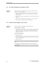
Page 48: ... Pointer Appears on the Screen The mouse pointer may not appear for the following reasons The mouse driver is not loaded S Check whether the mouse driver is correctly installed Check whether the mouse pointer is present when you start your user program Refer to the manuals for the mouse and user program to obtain detailed information about the mouse driver The mouse is not connected S Switch off y...

Page 49: ...ct after you switch off your PC and switch it back on again In this case please contact your technical support team Chapter 7 6 7 Rebooting Your Hard Drive Data Deleted Windows NT Note Applies only to devices with pre installed operating systems Follow the instructions given in the chapter on installation in the User s Guide Introducing Microsoft Windows NT To re install the supplied drivers and t...

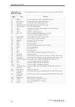
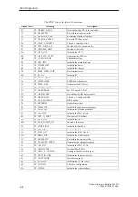
Page 50: ...ccessing drive A Contact your technical support team Diskette drive B error Error accessing drive B Contact your technical support team Failure fixed disk Error accessing the hard drive Contact your technical support team Keyboard error Check whether the keyboard is connected correctly Stuck key Check whether a key on the keyboard is stuck K system RAM failed at offset Memory error Contact your te...

Page 51: ...sequences In addition the individual self test steps are output at I O port 80h The optional SafeCard allows these outputs to be displayed in hexadecimal code at the front of the device Conversion table for the beep codes to hexadecimal representation Beeps Hex Code B B 0 B BB 1 B BBB 2 B BBBB 3 BB B 4 BB BB 5 BB BBB 6 BB BBBB 7 BBB B 8 BBB BB 9 BBB BBB A BBB BBBB B BBBB B C BBBB BB D BBBB BBB E B...

Page 52: ...the cache size 2A TP_ZERO_BASE Set 512k base RAM to 0 2C TP_ADDR_TEST Test the base RAM address cables 2E TP_BASERAML Check the 1 64k base RAM 38 TP_SYS_SHADOW BIOS shadow 20 TP_REFRESH Refreshcircuittest 29 TP_PMM_INIT Initialize the post memory manager 33 TP_PDM_INIT Initialize the dispatch manager C1 TP_7xx_INIT Initialize the PG 7xx I Os 09 TP_SET_IN_POST Start power ON self test 0A TP_CPU_INI...

Page 53: ...the cache configuration 6C TP_DISP_SHADOWS Configuration and size of the shadow Display RAM 6E TP_DISP_NONDISP Display non disposable segment 70 TP_ERROR_MSGS Display post error 72 TP_TEST_CONFIG Check SETUP irregularities 7C TP_HW_INTS Set the IRQ vectors 7E TP_COPROC Check whether the CO processor is present 96 TP_CLEAR_HUGE_ES Switch the ES back 80 TP_IO_BEFORE Disable IO circuits 88 TP_BIOS_IN...

Page 54: ...whether to activate setup AC TP_SETUP_CHEK Output any F1 F2 message AE TP_CLEAR_BOOT Cancel the self test flag B0 TP_ERROR_CHECK Check for any possible errors B2 TP_POST_DONE End of the self test BE TP_CLEAR_SCREEN Clear the screen B6 TP_PASSWORD Password query option BC TP_PARITY Cancel the parity memory bit BD TP_BOOT_MENU Display the boot menu option B9 TP_PREPARE_BOOT Prepare the boot C0 TP_IN...

Page 55: ...esentatives Please contact the authorized regional service department or authorized repair centers for all of your service needs The relevant addresses can be found at the end of this chapter For further support contact the SIMATIC Customer Support Hotline Chapter Overview 7 ...

Page 56: ...Time Mo Fr 0 00 to 24 00 Phone 49 911 895 7777 Fax 49 911 895 7001 GMT 01 00 The working languages of the SIMATIC Hotlines are generally English and German the Authorization Hotline can also be contacted in French Italian or Spanish The SIMATIC Customer Support team offers you substantial additional information about SIMATIC products via its online services S General current information can be obt...

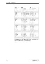
Page 57: ...ngen 49 9131 7 31048 49 9131 7 35263 Essen 49 201 816 1580 49 201 816 1522 Frankfurt 49 69 797 7358 49 69 797 7131 Hamburg 49 40 2889 4230 49 40 2889 4430 HanoverLaatzen 49 511 877 2241 49 511 877 1320 Karlsruhe 49 721 595 4183 49 721 595 6667 Langen 49 69 797 5608 49 69 797 5567 Leipzig 49 341 210 2049 49 341 210 2049 Mannheim 49 621 456 1328 49 621 456 1460 Munich 49 89 9221 6213 49 89 9221 6201...

Page 58: ...7577106 Italy 39 02 6676 3490 Japan 81 3 5423 8502 81 3 5423 8737 Mexico 52 5 328 2456 52 5 328 2058 Netherlands 31 70 333 3858 31 70 333 3878 Poland 48 22 670 9166 48 22 670 9169 Portugal 351 1 75 73234 351 1 75 89333 Singapore 65 740 7150 65 740 7196 South Africa 27 12 309 0149 27 12 309 0142 South Korea 82 2 3420 4880 82 2 3420 4889 Spain 34 91 514 8400 34 91 514 9217 Sweden 46 8 728 1462 46 8 ...

Page 59: ......

Page 60: ...1999 Printed in the Federal Republic of Germany Siemens AG Bereich Automatisierungs und Antriebstechnik GeschaeftsgebietIndustrie Automatisierungssysteme Postfach 4848 D 90327 Nuernberg Subject to change without prior notice C79000 Z7076 C814 ...

Reviews: