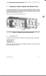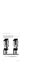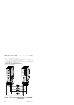
Expansion of Basic System with External I/Os
S5-95F
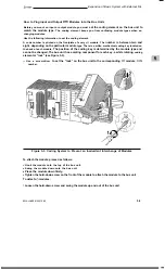
How to Install the Interface Module
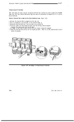
Hook the interface module to the standard mounting rail.
Swing the interface module back until the slide on the bottom snaps into place on the rail.
Use the flat ribbon cable to connect the module to the last bus unit.
Use connecting cable 712-8 to join the two interface modules.
Connect the cable to the "out" socket on the PLC tier and to the "in" socket on the expansion
tier.
Securely screw the connecting cable plugs in place.
Plug the caps onto the unused sub D connectors.
How to Remove the Interface Module
Only for IM 316: Loosen the hold-down screws from the plugs and remove the connecting cable.
Remove the connecting flat ribbon cable from the adjacent bus unit.
Use a screwdriver to press down on the slide located on the bottom of the interface module.
Swing the module up and out of the standard mounting rail.
5.3
Cabinet Mounting
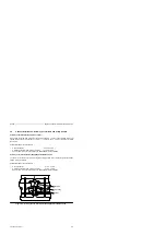
To improve noise immunity, the programmable controller should be mounted on a metal plate.
There should be electrical continuity between the grounded enclosure and the mounting rails. Make
sure that the system is bonded to earth.
You can use the 8LW system or the 8LX system mounting plates (see Catalog NV21).
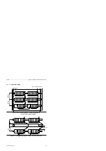
Adequate ventilation and heat dissipation are important to the proper operation of the system. You
must have at least 210 mm (8.3 in.) between each mounting rail (see Figures in Appendix B) for
proper ventilation.
Locate the programmable controller and the power supply on the lowest tier.
To provide adequate cabinet ventilation, define the total heat loss by calculating the sum of all typical
heat losses (see Catalog ST 52.1).
5-6
EWA 4NEB 812 6210-02

