Operations List
S5-95F
C-16
EWA 4NEB 812 6210-02
C.3
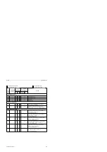
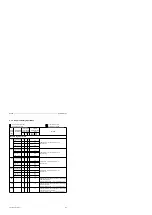
List of Abbreviations
Abbreviation
Explanation
Permissible Operand Value Range for
S5-95F
ACCU 1
Accumulator 1
(When accumulator 1 is loaded,
any existing contents are shifted
into accumulator 2.)
ACCU 2
Accumulator 2
BN
Byte constant (fixed-point number)
(- 127 to +127)
C
Counter
- retentive
- non-retentive
- for the ”Bit Test” and ”Set” supplementary
operations
(0 to 7)
(8 to 127)
(0 to 127)
(0.0 to 127.15)
CAN
DB1 parameter: counter A counts with negative and
positive edge
CAP
DB1 parameter: counter A counts with positive edge
CBN
DB1 parameter: counter B counts with negative and
positive edge
CBP
DB1 parameter: counter B counts with positive edge
CC 0 / CC 1
Condition code 0 / Condition code 1
CCN
DB1 parameter: cascaded counter counts with
negative edge
CCP
DB1 parameter: cascaded counter counts with
positive edge
CF
DB1 parameter: input correction factor (integral real-
time clock)
CLK
DB1 parameter: clock data location
CPU
Central processing unit of programmable controller
CSF
STEP 5 control system flowchart method of
representation
D
Data (1 bit)
(0.0 to 255.15)
DB
Data block
(2 to 255)
DL
Data word (left-hand byte)
(0 to 255)
DR
Data word (right-hand byte)
(0 to 255)
DW
Data word
(0 to 255)
EF
DB1 parameter: SINEC L1, position of receive
mailbox
F
Flag
- retentive
- non-retentive
(0.0 to 63.7)
(64.0 to 255.7)
FB
Function block
(0 to 255)
FB/FY
Flag byte
- retentive
- non-retentive
(0 to 63)
(64 to 255)
Formal operand
Expression with a maximum of 4 characters. The first
character must be a letter of the alphabet.


