S5-95F
Design, Functions and Operation
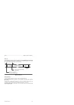
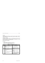
Data Cycle
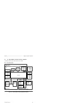
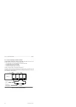
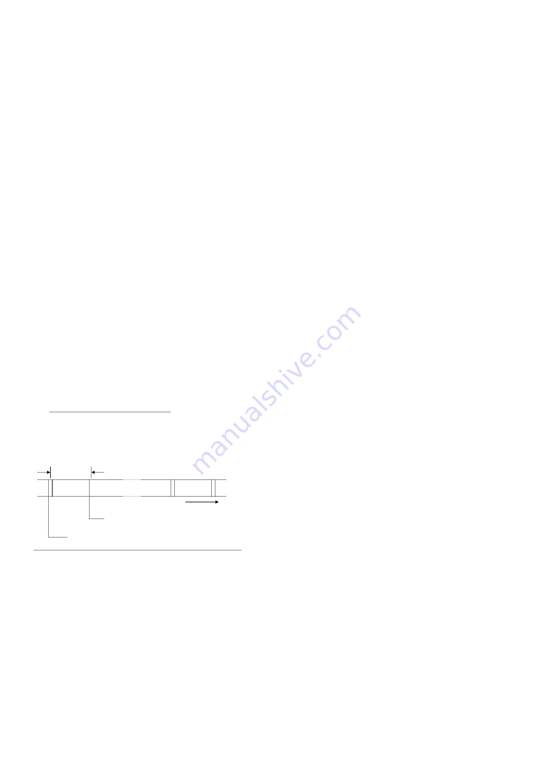
Prior to a program scan, the external I/O bus transfers the current information of the input modules
to the process image input table (PII). At the same time, the information contained in the process
image output table (PIQ) is transferred to the output modules.
Figure 2-7. Data Cycle
a a a a a a a a a a a a a a a
a a a a a a a a a a a a a a a
a a a a a a a a a a a a a a a
a a a a a a a a a a a a a a a
a a a a a a a a a a a a a a a
a a a a a a a a a a a a a a a
Time axis
Shift
data
Data cycle
a a a
a a a
a a a
a a a
a a a
a a a
a a a
a a a
a a a
a a a
a a a
a a a
a a a
a a a
a a a
a a a
a a a
a a a
a a a
a a a
Program scanning
a a a
a a a
a a a
a a a
a a a
a a a
a a a
a a a
a a a
a a a
Shift
data
a a a
a a a
a a a
a a a
a a a
a a a
a a a
a a a
a a a
a a a
Load data from the input
modules into the shift register
Transfer data from shift register to
output modules
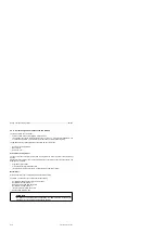
Interrupt Data Cycle
There is an interrupt input data cycle prior to each time-controlled program scan.
Before a time-controlled program scan (OB 13), current information of the input modules is read into
the interrupt PII.
Following a time-controlled program scan (OB 13), there is not an interrupt output data cycle until
data has been moved into the interrupt PIQ via a transfer operation (see section 8.1.3).
Information is output from the interrupt PIQ to the output modules during an interrupt output data
cycle. The PIQ is updated.
EWA 4NEB 812 6210-02
2-9

