Installing and Connecting the Basic System
S5-95F
4.4
Onboard Interrupt Inputs
There are two different types of onboard interrupts on the S5-95F:
•
Onboard OB2 interrupts
•
Onboard OB3 interrupts
Connection and parameterization of the interrupt inputs are described in Chapter 12 ("Interrupt
Processing").
Supply Voltage for Interrupt Inputs (9-Pin Sub D Connector)
Please refer to section 4.6.
4.5
Onboard Counter Inputs
The S5-95F is provided with two separate counter inputs. You must program these inputs with COM
95F in order to be able to use them.
Each counter input is internally assigned a 16-bit counter register. The counter registers count the
pulses that are received at the enabled counter inputs. When a comparison value, which can be
preset in DB1, is reached, the S5-95F calls OB3.
In the following text, we differentiate between counter inputs and counter registers only when
necessary. Otherwise, we briefly refer to counter A and counter B.
Maximum Operating Frequency and Signal Duration
The counter inputs are 24 V DC inputs. The maximum operating frequency depends on the
amplitude of the counting pulses and reaches its maximum at between 24 and 28 V. The maximum
operating frequency for counting pulses with an amplitude of between 24 and 28 V is 350 Hz.
To ensure that the S5-95F recognizes an active counter signal reliably, the signal levels "0" and "1"
must at least have a duration of 1.4 ms (bouncing of the sensor contacts is not permissible).
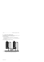
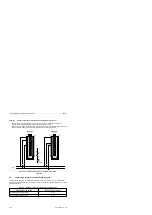
Supply Voltage for Counter and Interrupt Inputs (9-Pin Sub D Connector)
Please refer to section 4.6.
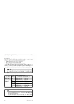
Sensor Requirements for Onboard Counters
The following sensors are permissible for onboard counters:
•
Single-channel, failsafe sensors
•
Two-channel sensors, with contacts operating in synchronism so that the same circuit states are
possible within approx. 1 ms for all frequencies occurring during operation.
Discrepancy between the Counter Inputs
The discrepancy time for both counters is permanently set to approx. 1 ms. During this period, the
S5-95F tolerates different counter statuses in both subunits. If the counter statuses in the two
subunits are faulty for longer than 1 ms, the S5-95F responds with a fault signal and with the
programmed system reaction.
4-18
EWA 4NEB 812 6210-02


