Hardware
Installation
Use in
the S5-135U/S5-150U and S5-155U
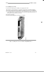
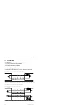
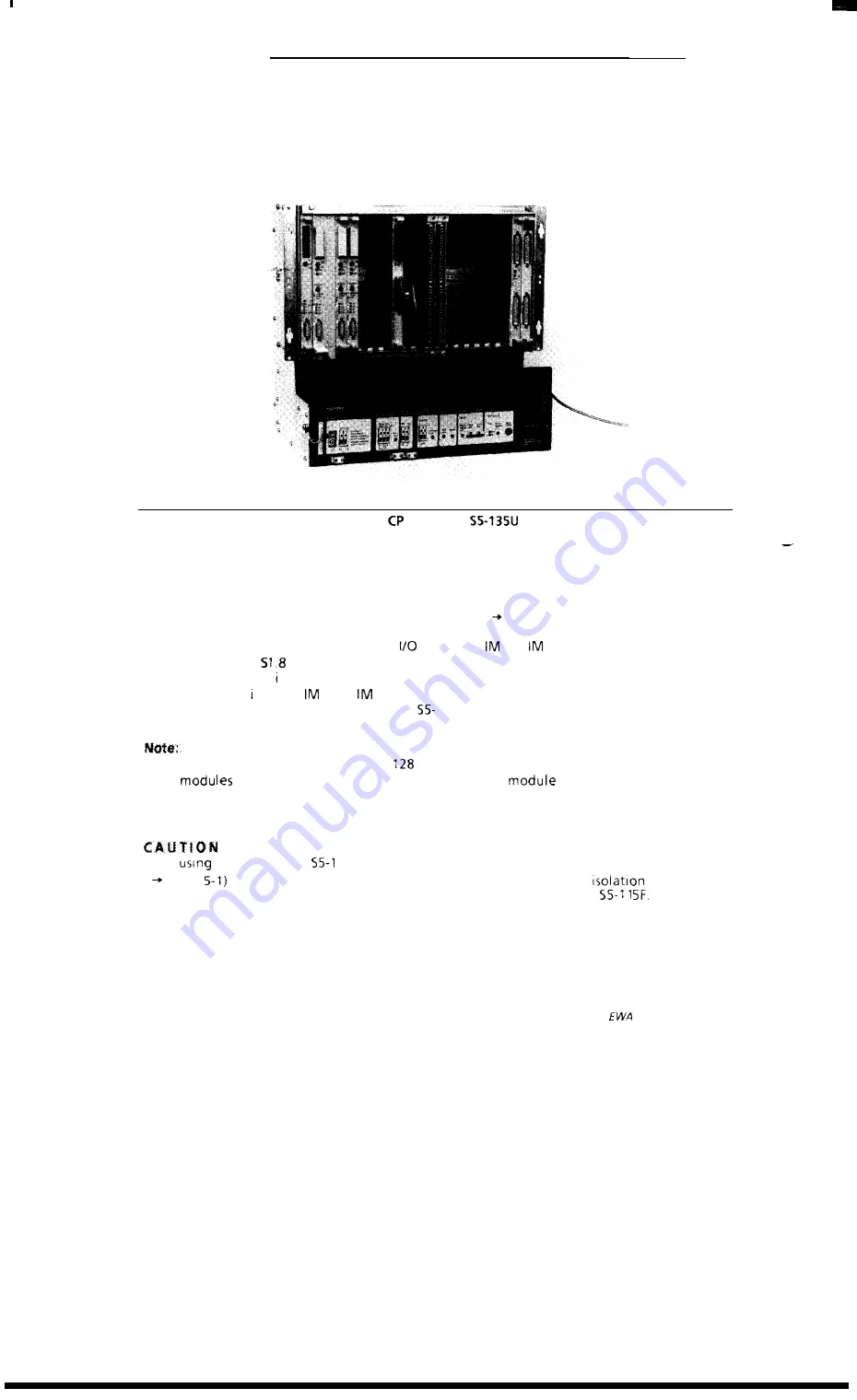
The CP 523 is mounted direct onto the module rack.
CP
523
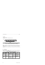
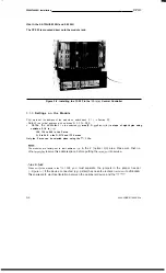
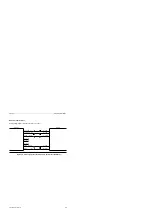
Figure 3-2. Installing the
523 in the
Central Controller
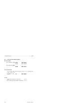
3.1.3 Settings on the Module
You
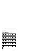
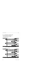
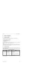
must set the address of the module on switch bank S 1 (
Section
5 ) :
. Select
the initial address with switches
S 1.1 to S1.5
●
Define the addresses
i n the selected
area (P, O,
3 or
4) in steps of eight bytes using
switches S 1.6 to
128, 136 to 248 n the P area
O, 8 to 248 n the O,
3 and
4 areas
Only the P area can be selected when using the
1 15u.
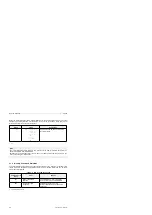
The modules are factory-set to start address
in the P (normal 1/0) area. Make sure that no
other
reserve this address space before putting the
into service.
:
When
the module in the
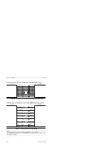
15F, you must separate the jumpers in the jumper header
( Figure
if the device connected (e.g. printer) has no safe electrical
to VDE 0160.
This ensures safe electrical Isolation between the peripheral device and the
3-4
4NEB811 6044-02a


