4-35
ET 200U Distributed I/O Station
EWA 4NEB 812 6087–02b
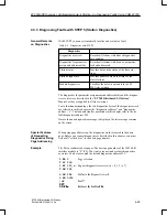
Module diagnostics tells you which module in the ET 200U slave station is
faulty.
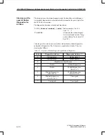
L KY n,4
T PW 252
The number of the slave station (n = station number) from
which module diagnostics is requested must be stored in
the
“diagnostics
address”
byte;
in
the
“diagnostics
address
+ 1” byte, the code for “header” and “module diagnostics
(slots 0 to 7)” (= 4) is to be stored
or
L KY n,5
T PW 252
“Module diagnostics (slots 8 to 15) and (slots 16 to 23)”
(= 5)
or
L KY n,6
T PW 252
“Module diagnostics (slots 24 to 31)” (= 6)
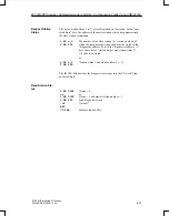
The IM 308–B interface module then writes the diagnostics message into the
I/O word “diagnostics address”.
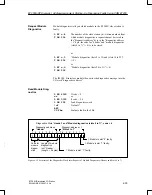
L KH 4500
or
L KH 0000
L PW 252
!=F
BEC
JU FBx
If code = 4
or
if code = 5, 6
Load diagnostics word
No fault?
Evaluate fault in the FBx.
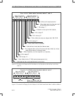
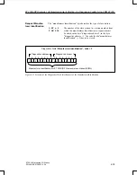
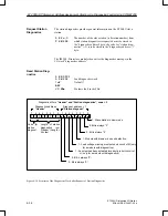
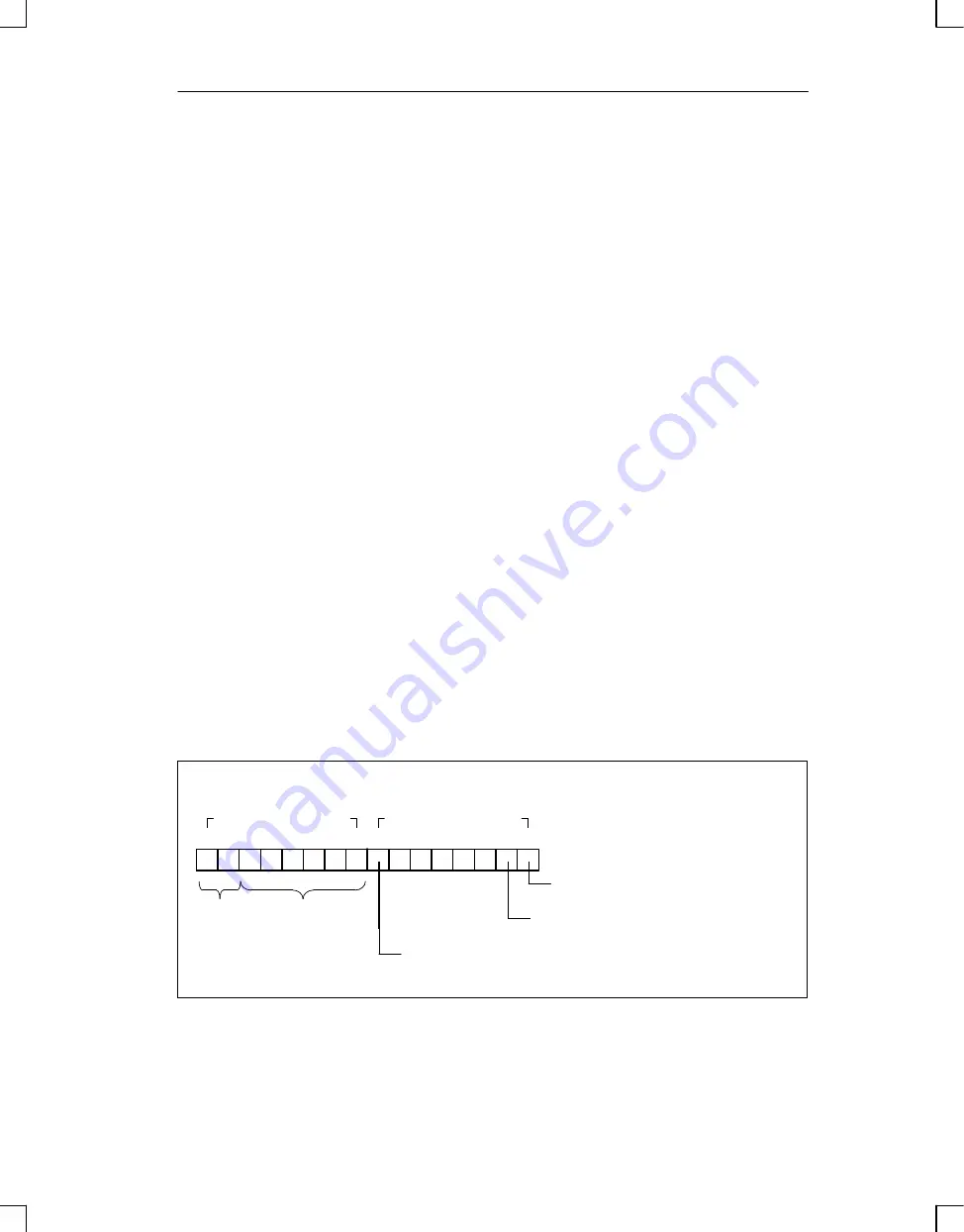
Diagnostics Word “Header” and “Module diagnostics (slots 0 to 7)”, code = 4
7
6
5
4
3
2
1
0
7 6
5
4
3
2
1
0
Diagnostics address
“Header”
Diagnost. a 1
“Slots 0 to 7”
e für
grup–
diag–
e
Length of module
diagnostics
incl. “Header”
(Length = 5 bytes)
0
1
0
0
0
1
0
1
1: Module in slot “7” faulty.
1: Module in slot “1” faulty.
1: Module in slot “0” faulty.
Code for
module
diagno-
stics
Figure 4-15 Structure of the Diagnostics Word after Request of Module Diagnostics (Header and Slots 0 to 7)
Request Module
Diagnostics
Read Module Diag-
nostics
ET 200U(DP Siemens): Address Assignment,Starting–Up,Diagnosing Faults Using COM ET200

