5-7
ET 200U Distributed I/O Station
EWA 4NEB 812 6087–02b
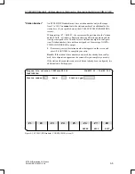
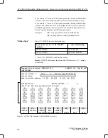
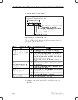
6. Assign a station name if desired (all keyboard characters are permissible).
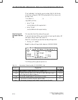
Under the “Station name” field is the “Next available address” field with
areas for four entries. When you configure for the first time in the program
file that you set up, all four first available addresses are assigned as 0.
If a slave station has already been configured, each entry field shows the ad-
dress of the first available byte for the following areas:
DI
(digital input modules)
DQ
(digital output modules)
AI
(analog input modules)
AQ
(analog output modules)
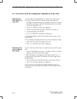
COM ET 200 updates the “Next available address” input fields immediately
after you enter a valid address ID for a slot in the “Configuration” field of
this screen.
However, before you configure an ET 200U (DP Standard) slave station, you
must take the following steps:
Separate the areas for digital and analog modules so that addresses do not
overlap. Communications processors (CPs) and intelligent I/O modules
(IPs) count here as analog modules.
Determine the structure of your stations. Additions and changes that you
make later result in address assignments that can be confusing to read or
otherwise unclear.
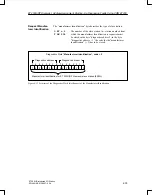
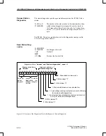
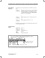
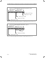
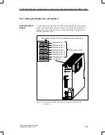
CPUs 941, 942, 943 and 944 of the S5–115U/H PLC series generate the pro-
cess I/O image word–by–word. This may result in
two slave stations being addressed within one word
or
the address of the first slave station ending exactly in the middle of one
word and the address of the second slave station starting at the same posi-
tion.
Station 1
Station 2
Address 0:
1:
2:
3:
4:
Station 1
Station 2
Address 0:
1:
2:
3:
4:
PII
PIQ
Station 2
Station 2
Station 2
Station 2
Station 2
Station 2
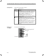
Figure 5-4 Example of Process I/O Image with ET 200
“Next Available
Address”
Special Address
Assignment
Conditions
ET 200U(DP Standard): Address Assignm.,Starting–Up, Diagnosing Faults Using COM ET 200


