5-33
ET 200U Distributed I/O Station
EWA 4NEB 812 6087–02b
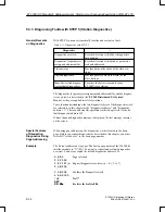
The station status, the station diagnostics and the identifier–related diagnos-
tics (module diagnostics) are described in this manual as they are typical for
the ET 200U slave station.
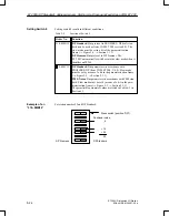
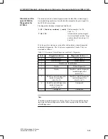
The diagnostics function is loaded and transferred:
L KY (Station number),(code)
Station number: 3 to 124
Code: 0, ..., 7
T PW 252
Afterwards the station diagnos-
tics is transferred into the “diag-
nostics address” byte (here I/O
byte 252)
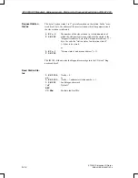
16 bytes per slave station are reserved for station status, station diagnostics
and module diagnostics. The 16 bytes are organized in 8 words. They are
structured as follows:
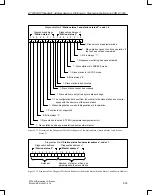
Table 5-12 Structure of Station Diagnostics and Module Diagnostics
Code
Diagnostics Address
Diagnostics A 1
0
Station status 1
Station status 2
1
Station status 3
Master address
2
Manufacturer identification
3
Header
Station diagnostics
4
Header
Identifier–related diagnostics
(module diagnostics)
(slots 0 to 7)
5
Identifier–related diagnostics
(module diagnostics)
(slots 8 to 15)
Identifier–related diagnostics
(module diagnostics)
(slots 16 to 23)
6
Identifier–related diagnostics
(module diagnostics)
(slots 24 to 31)
Unassigned
7
Unassigned
Unassigned
Note
If a module signals diagnostics, a delay of up to 150 ms is possible between
input into the station diagnostics and the following input into the identifier–
related diagnostics.
Structure and Re-
quest of Station
Diagnostics for
ET 200U
ET 200U(DP Standard): Address Assignm.,Starting–Up, Diagnosing Faults Using COM ET 200

