6-7
ET 200U Distributed I/O Station
EWA 4NEB 812 6087–02b
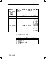
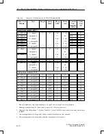
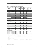
Table 6-4
Differences Between the Various Modes of the IM 318–C (Continued)
Characteristics
ET 200U
(DP Standard)
ET 200U(FMS)
ET 200U in a
Mixed Config.
Combi–Slave
Access to FMS objects:
DP inputs
DP outputs
FMS inputs
FMS outputs
Irrelevant
Irrelevant
Irrelevant
Read
Read / write
Read
Read
Irrelevant
Irrelevant
Read
Read
Read
Read / write
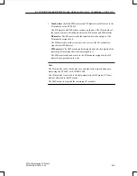
Meaning of BF LED
(BUS FAULT):
Table 5-10,
Section 5.3.1
Table 6-39,
Section 6.4
Table 6-39,
Section 6.4
Table 6-39,
Section 6.4
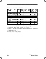
Failure of the DP master
All outputs are
set to “0”.
1
–
All outputs are
set to “0”.
1
Outputs assigned
to the DP master
are set to “0”.
1
The states of the
outputs assigned
to the FMS mas-
ter are retained.
Failure of the FMS mas-
ter
–
All outputs are
set to “0”.
2
No influence on
ET 200U
Outputs assigned
to the FMS mas-
ter are set to
“0”.
2
The states of the
outputs assigned
to the DP master
are retained.
1: After response monitoring time has elapsed.
2: After link monitoring time has elapsed.
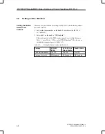
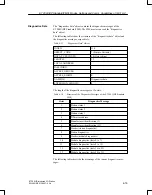
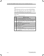
The IM 318–C can be operated as DP Standard slave and/or FMS slave:
If the IM 318–C is Operated as ...
... Refer to
ET 200U(DP Standard)
Section 5
ET 200U(FMS)
ET 200U in a mixed configuration
Combi–slave
Section 6.2
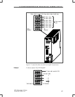
ET 200U(DP Standard/FMS): Modes, Settings and Comm. Capabilities of IM 318–C

