7-3
ET 200U Distributed I/O Station
EWA 4NEB 812 6087–02b
7.2
Connecting Current and Voltage Sensors to Analog Input Modules
Observe the following rules to connect current and voltage sensors to analog
input modules:
When you have multi–channel operations, assign the channels in ascend-
ing order. This shortens the data cycle.
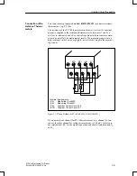
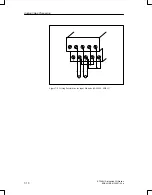
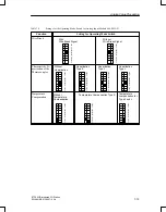
Use terminals 1 and 2
–
for the connection of a compensating box (464–8MA11)
or
–
for the supply of two–wire transducers (464–8ME11).
Terminals 1 and 2 cannot be used with the remaining analog input mod-
ules.
Short–circuit the terminals of unused inputs to increase interference im-
munity.
The potential difference between the common references of the inputs
must not exceed 1 V. To prevent this, set the reference potentials of the
sensors to a common reference potential.
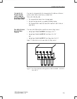
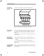
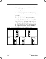
Module 464–8MA11/8MA21 is recommended for voltage measurement with
thermocouples. With floating sensors (e.g., isolated thermocouples), the per-
missible potential difference V
CM
between the minus terminals of the inputs
and the potential of the standard mounting rail must not be exceeded. To
avoid this, the negative potential of the sensor must be connected to the cen-
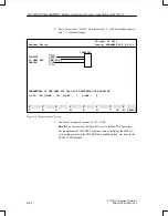
tral grounding point (see Figure 7-1).
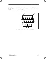
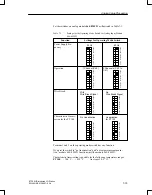
Jumper terminals 1 and 2 together if you do not use compensation boxes.
Voltage Measure-
ment with Isola-
ted / Non–Isolated
Thermocouples
Analog Value Processing


