7-8
ET 200U Distributed I/O Station
EWA 4NEB 812 6087–02b
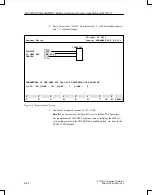
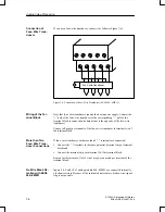
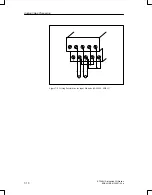
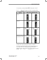
If you use a four–wire transducer, connect it as follows (Figure 7-6):
1
3
5
7
9
2
4
6
8
10
Four–wire transducer
U
– +
– +
– +
– +
Figure 7-6 Connection of Four–Wire Transducers (6ES5 464–8ME11)
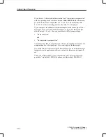
Note that four–wire transducers require their own power supply. Connect the
“+” pole of the four–wire transducer to the corresponding “–” pole of the
terminal block (a connection technique that is the opposite of the two–wire
transducer).
Connect all negative terminals of the four–wire transducer to terminal two of
the terminal block.
If four–wire transducers with more than 2 “–” terminals are connected:
Connect the “–” terminals to the same potential (terminal strip or terminal
block) and
Connect the terminal strip with terminal 2 of the terminal block.
Reason for this measure: Only 2 wires may be connected per terminal of the
terminal block.
Inputs 4, 6, 8 and 10 of analog module 464–8ME11 are connected internally
via shunt resistors. Because of the internal shunt resistors, broken wire signal-
ling is not possible.
Connection of
Four–Wire Trans-
ducers
Wiring of the Ter-
minal Block
More than Two
Four–Wire Trans-
ducer Connections
No Wire Break De-
tection with 6ES5
464–8ME11
Analog Value Processing

