7-9
ET 200U Distributed I/O Station
EWA 4NEB 812 6087–02b
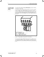
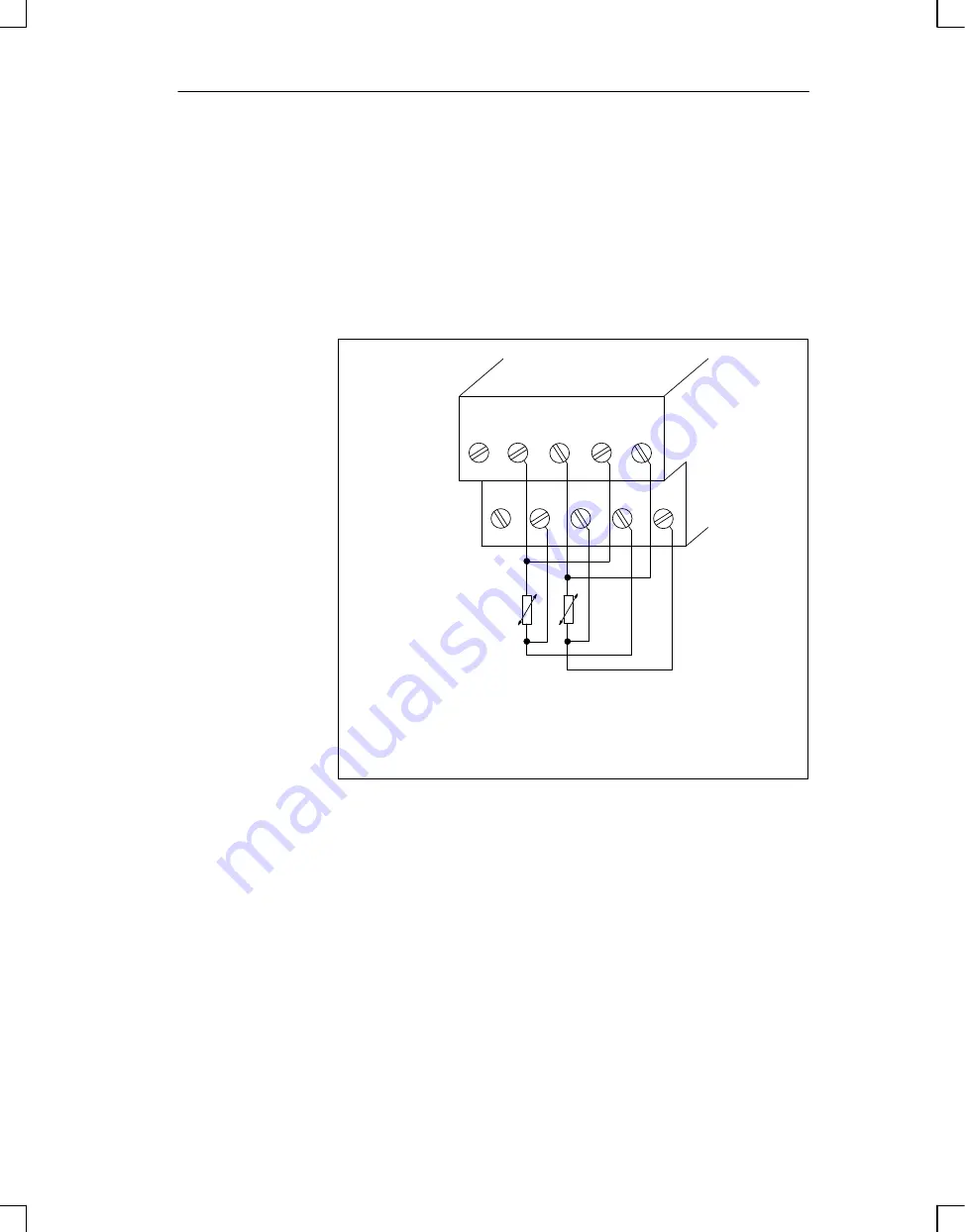
You can use analog input module 464–8MF11/8MF21 to connect resistance
thermometers (e.g. PT 100).
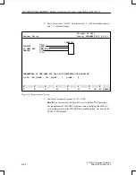
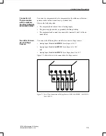
The resistance of the PT 100 is measured in a four–wire circuit. A constant
current is supplied to the resistance thermometer via terminals 7 and 8 as
well as via terminals 9 and 10, so that voltage drops in these constant current
circuits do not affect the measurement results. The measuring inputs have a
high resistance so that only a negligible current loss develops in the measur-
ing circuits.
1
2
M0
+
M1
+
I
C
0
+
I
C
1
+
3
5
7
9
4
6
8
10
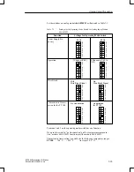
Terminal Assignments
(3/4):
Measuring Circuit M0
(5/6):
Measuring Circuit M1
(7/8):
Constant Current Circuit I
C
0
(9/10):
Constant Current Circuit I
C
1
Figure 7-7 Wiring Method for PT 100 (6ES5 464–8MF11/8MF21)
If you use only one channel for PT 100 measurement (e.g., channel 0), you
can use the other channel for voltage measurement (
500 mV). In this case,
use terminals M+/M– for the signal connection and short circuit terminals I
C+
and I
C–
.
Connection of Re-
sistance Thermo-
meters
Analog Value Processing

