7-11
ET 200U Distributed I/O Station
EWA 4NEB 812 6087–02b
7.3
Start–Up of Analog Input Modules
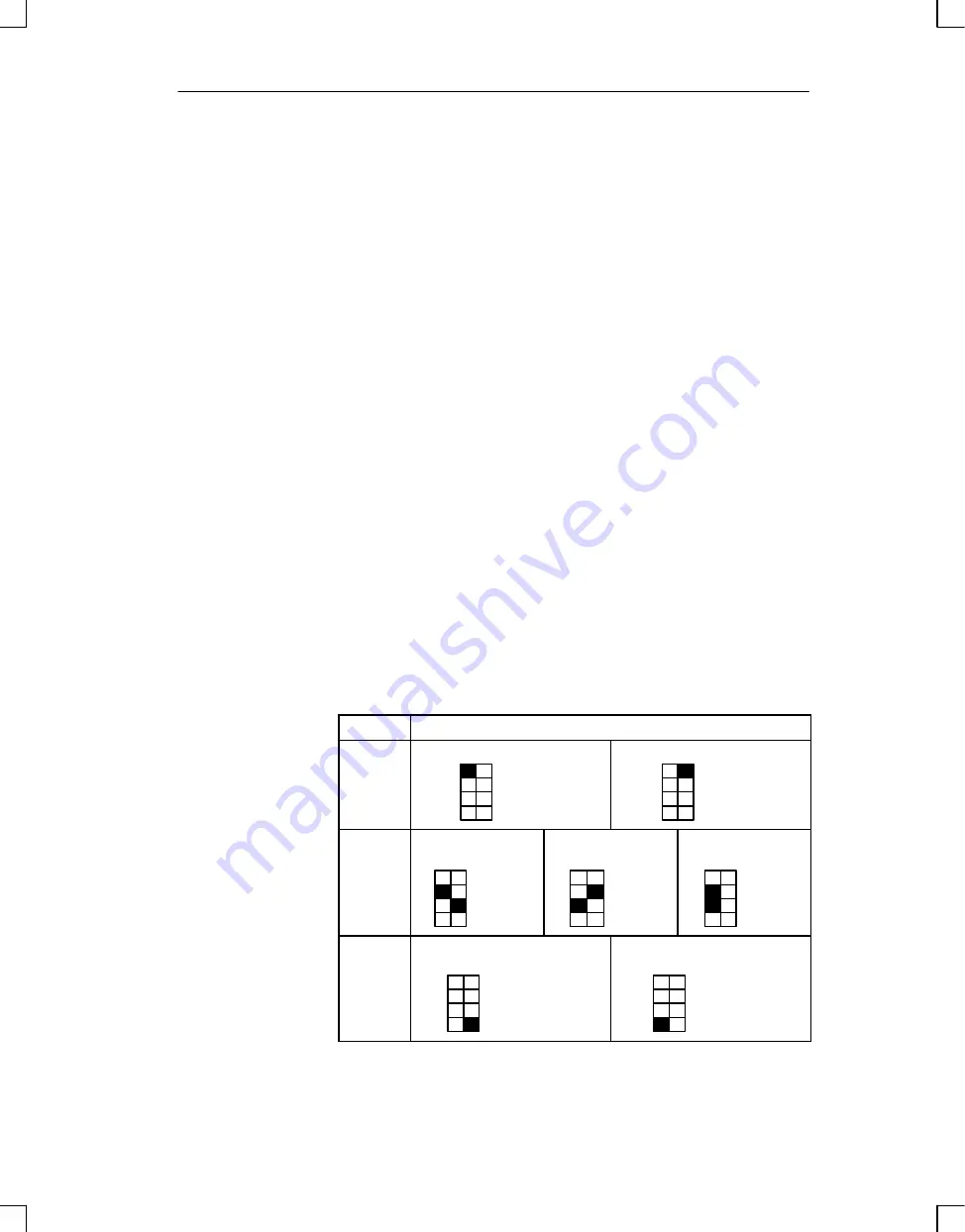
When using analog input modules 464–8 through 11, set the intended operat-
ing mode using the switches on the front panel. These switches are located on
the right side at the top of the front panel of the module.
Set the switch to the available power supply frequency. This selects the in-
tegration time of the A/D converters for optimal interference voltage suppres-
sion. The frequencies are as follows:
Power frequency 50 Hz
³
Integration time 20 ms
Power frequency 60 Hz
³
Integration time 16.66 ms
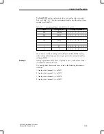
Set the number of channels you wish to assign on the input module. If there
are fewer than four channels, less address space will be assigned and meas–
ured values will be updated faster.
Once you activate the broken wire signal, a break in one of the lines to the
sensor (thermocouple or PT 100) or in the sensor itself causes the red LED
above the function selection switch to light up. At the same time, the broken
wire error bit F (bit 1, byte 1) for the faulty channel is set.
The module recognizes a wire break by applying a conventional tripping cur-
rent to the input terminals and comparing the resulting voltage to a limit va-
lue. If there is a wire break in the sensor or the lines, the voltage exceeds the
limit value and a “wire break” signal is sent. When the signal at the input is
measured with a digital voltmeter, the tripping current pulses cause apparent
fluctuations of the signal. Deactivation of the wire break signal does not turn
off the tripping current.
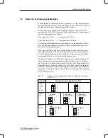
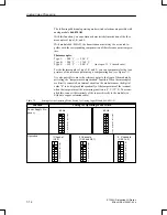
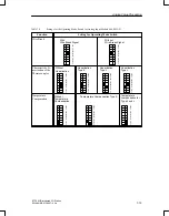
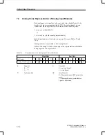
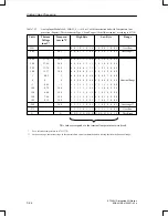
Table 7-1
Settings for the Operating Mode Switch for Analog Input Modules
464–8 to 11
Function
Settings for Operating Mode Switch
Power
Supply
Fre-
quency
50 Hz
4
3
2
1
60 Hz
4
3
2
1
Opera-
tion
1 Channel
(Ch 0)
4
3
2
1
2 Channels
(Ch 0 and Ch 1)
4
3
2
1
4 Channels
(Ch 0 to Ch 3)
4
3
2
1
Wire
Break
With
Wire Break Signal
4
3
2
1
No
Wire Break Signal
4
3
2
1
Analog Value Processing

