9-3
ET 200U Distributed I/O Station
EWA 4NEB 812 6087–02b
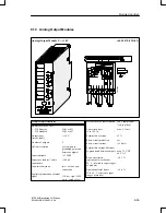
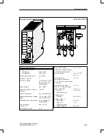
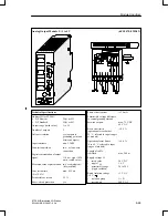
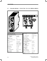
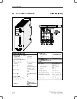
The module has two isolated comparators for voltage or current measurement
(selector switch with positions U/0/I). When the preset value is reached, the
LED of the respective channel lights up and sends a 1 signal to the program-
mable controller.
Remove the module or disconnect the measuring circuit before you select the
function.
In switch position “0”, the comparator is switched off; if the comparator is
scanned, a “0” signal results.
You set the response threshold of the comparator using a selector on the front
panel. The selector has scale divisions to simplify adjustment.
You install the comparator module on a bus unit like any other input or out-
put module.
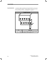
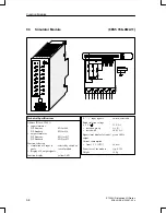
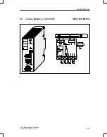
See schematic diagram. Unused inputs can be left open.
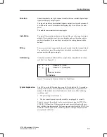
The comparator module is addressed like a two–channel digital input module
(channel 0 or 1, see Figure 9-1).
A
I
x.0
Channel “0” ; Scan (Examples)
O
I
x.1
Channel “1” ;
Channel Number
Slot Address
Figure 9-1 Scanning the Comparator Module
Function
Installation
Wiring
Addressing
Function Modules

