9-20
ET 200U Distributed I/O Station
EWA 4NEB 812 6087–02b
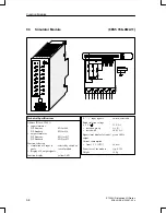
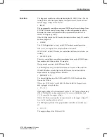
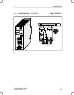
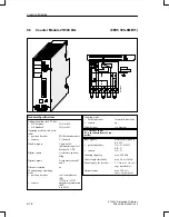
The counter module can be used as an up–counter or as an up/down counter
for a position decoder.
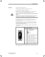
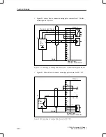
The counting pulses are supplied by a sensor that you can connect to the
15–pin subminiature D female connector of the module. You can choose
from two types of sensors that fulfill the following requirements:
5 V error voltages according to RS 422 (up to 500 kHz) or
24 V signals (up to 25 kHz).
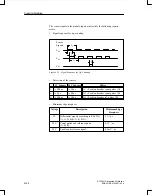
As additional inputs, the module has an enable input and a reference input.
By using the STEP 5 program, you can assign two setpoints via the I/O bus.
These setpoints are output to channels 0 and 1 in the I/O slot for the module.
Once the counter status reaches one of these values, the respective output
completes the circuit at the terminal block (Q0 or Q1). The status of the out-
puts is displayed in the diagnostics byte.
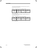
You can also read the following values by using the STEP 5 program:
The updated count
The diagnostics byte
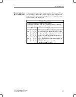
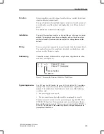
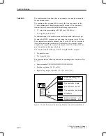
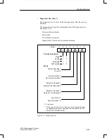
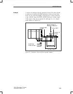
You can preselect the following items on the operating mode switch (see Fig-
ure 9-7):
Function mode (COUNTER/POSITION DECODING)
Position resolution (X1, X2, or X4)
Input voltage range of the sensor (5 V DC or 24 V DC)
Position decoding (PD)
Counter (C)
Pos. resolution
single
Pos. resolution
double
Pos. resolution
quadruple
not allowed
Sensor connection
5 V
Sensor connection
24 V
2
4
24 V
Figure 9-7 Switch Positions on the Operating Mode Switch of the Counter Module
Function
Function Modules


