9-24
ET 200U Distributed I/O Station
EWA 4NEB 812 6087–02b
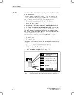
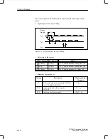
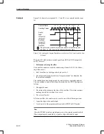
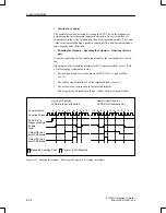
The sensor signals to the module inputs must satisfy the following require-
ments:
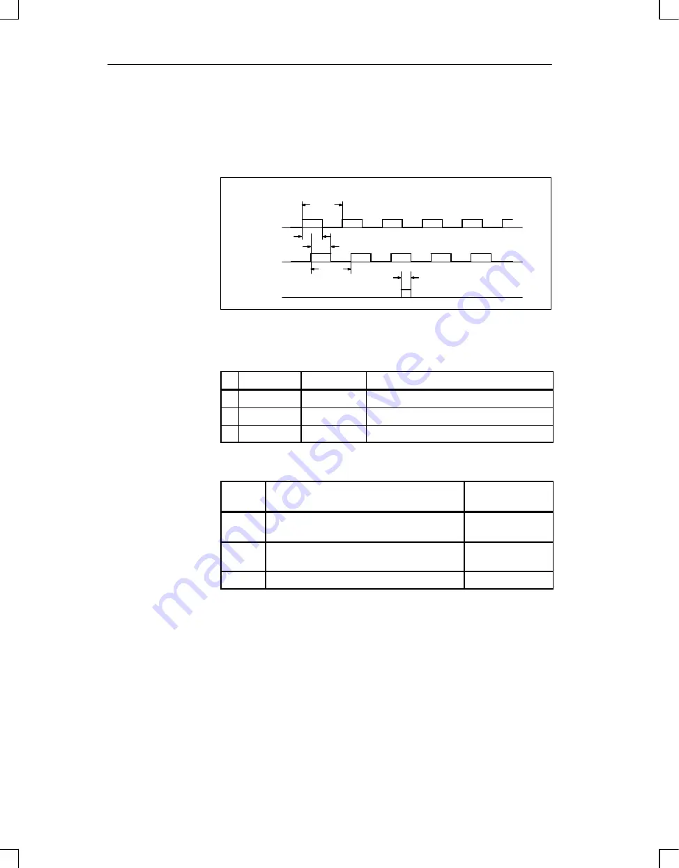
Signal sequence for up–counting
t
1
t
t
t t
t
2
Sensor
Signals:
V
a2
V
a0
V
a2
t
1
Figure 9-13 Signal Sequence for Up–Counting
Pulse time of the sensors
5 V Sensors
24
V
Sensors
Pulses
t
w
500 ns
w
10
m
s
V
a1
= Position decoder count pulses (A)
t
1
w
2
m
s
w
40
m
s
V
a2
= Position decoder count pulses (B)
t
2
w
500 ns
w
10
m
s
V
a0
= Position decoder ref. pulses (R)
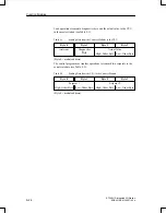
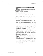
Minimum edge steepness
Voltage
Description
Minimum Edge
Steepness
5 V
Differential signals according to RS 422A
(A, A–N, B, B–N, R, R–N):
5
V /
m
s
24 V
Count pulses and reference pulse
(A, B, R):
0,3 V /
m
s
24 V
Enable and reference signal:
0,3 mV /
m
s
Function Modules

