9-28
ET 200U Distributed I/O Station
EWA 4NEB 812 6087–02b
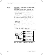
In the operation mode COUNTER, the module works as a “port–controlled”
up–counter and counts the positive edges of the counting pulses while the
enable input is high. If the counter reaches a preselected setpoint, the respec-
tive output is then enabled.
Initial Settings
On the operating mode switch, make the following selections:
COUNTER (C)
Counting pulse signal level (5 V or 24 V)
The position of the switches for position resolution is irrelevant.
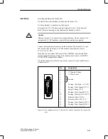
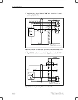
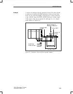
For this operation, you need a counting pulse sensor (e.g., BERO). The
pulses can be applied as 5 V differential signals according to RS 422A (up to
500 kHz) or as 24 V signals (up to 25 kHz). The sensor is connected to the
sub–D interface of the module.
Loading Setpoints
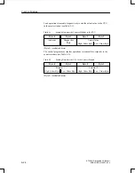
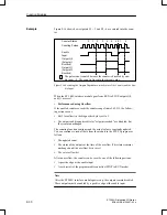
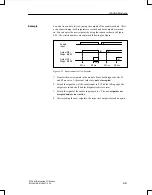
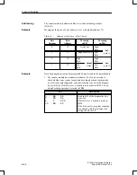
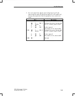
The control program can transfer two setpoints to the module. These set-
points must be in the range of 0 to 65,535.
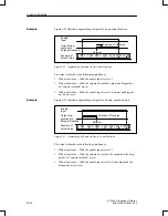
The transfer of the setpoints via the module depends on whether the “setpoint
1 (setpoint 2) reached“ bit is set in the diagnostics byte.
If the bit is not set, which means the existing setpoint has not been reached or
has not been exceeded, the new setpoint is transferred immediately and is
immediately valid.
If the bit is set, which means the existing setpoint has been reached or ex-
ceeded, the new setpoint is valid only after a positive edge occurs at the ena-
bled input.
If you do not specify a setpoint, a setpoint of 0 applies.
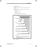
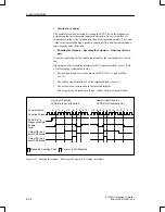
Enabling the Counter
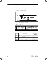
The signal state of the enable input (terminal 3 on the terminal block) deter-
mines the function of the counter.
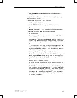
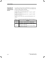
A positive edge at the enable input does the following:
Sets the counter to 0
Resets the diagnostics bits for “setpoint reached”
Resets the outputs
Enables the counter
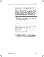
Note
The
enable
input
should
be
set to 1 only after the setpoint has been transferred.
Otherwise,
the
outputs
are
enabled
automatically
when
the
first
positive
edge
occurs.
Functional Des-
cription of the CO-
UNTER Mode
Function Modules

