9-30
ET 200U Distributed I/O Station
EWA 4NEB 812 6087–02b
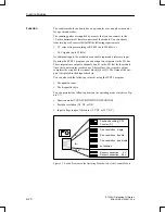
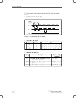
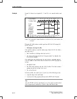
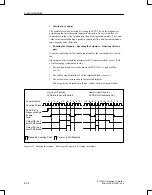
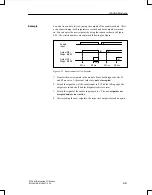
Figure 9-16 shows how setpoints S1 = 2 and S2 = 4 are entered into the coun-
ter.
ÉÉ
ÉÉ
ÉÉ
ÉÉ
ÉÉ
ÉÉ
ÉÉ
ÉÉ
0
1
2
3
4
5
5
0 1
2
Counter Status
Counting Pulses
Enable
Input
Output Q0
(Setpoint 1
Reached)
Output Q1
(Setpoint 2
Reached)
The pulse is not counted because the counter is disabled by ena-
ble input = 0. The count is frozen to the current value.
Figure 9-16Switching the Outputs Dependent on the Status of the Counter and the Ena-
ble Input
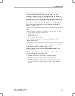
When the ET 200U interface module goes from RUN to STOP, outputs Q0
and Q1 are reset.
Performance during Overflow
If the enabled counter exceeds the counter range limit of 65,535, the follow-
ing actions occur:
Bit 3 (overflow) in the diagnostics byte is set to 1.
The
outputs
and
diagnostics
bits
for
“setpoint reached”
are disabled, but
they remain unchanged.
The counting function continues and the actual value is constantly updated.
You can continue to read all data from the module in the STEP 5 program as
follows:
The updated count
The status of the outputs at the time of the overflow (This status remains
unchanged until the overflow bit is reset.)
The set overflow bit
After an overflow, the counter can be reset by one of the following actions:
A positive edge at the enable input
A cold restart of the programmable controller (STOP to RUN mode)
Note
After the ET 200U interface module powers up, the outputs remain disabled.
These outputs must be enabled by a positive edge at the enable input.
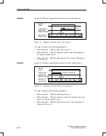
Example
Function Modules


