9-34
ET 200U Distributed I/O Station
EWA 4NEB 812 6087–02b
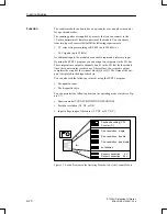
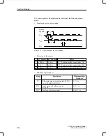
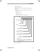
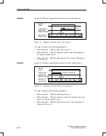
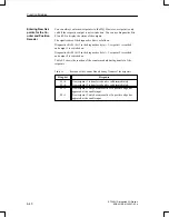
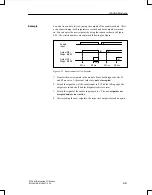
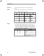
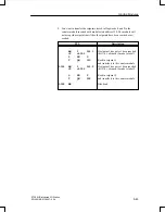
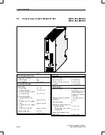
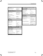
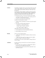
Figures 9-17, 9-18, and 9-19 illustrate different possibilities for a reference
traversing path.
Reference
Signal
Reference
Pulse of
the Sensor
Sync
Bit
Positive Direction of Traverse
Figure 9-17 Position
of
the
Reference
Point
(SYNC Bit 0=1) within the
Reference
Signal
Range
Reference
Signal
Reference
Pulse of
the Sensor
(1) First reference pulse detected by the module after the
leading edge of the reference signal
Sync
Bit
(1)
Figure 9-18 Position of the Reference Point (SYNC Bit=1) after the Reference Signal
Reference
Signal
Reference
Pulse of
the Sensor
(1) First reference pulse detected by the module after the
leading edge of the reference signal
Reference
Signal
Reference
Pulse of
the Sensor
Sync
Bit
Change of Direction
Positive Direction of Traverse
(1)
Figure 9-19 Position of the Reference Point (SYNC Bit=1) during a Reversal of
Direction before Reaching the Reference Pulse in a Positive Direction
Function Modules

