9-39
ET 200U Distributed I/O Station
EWA 4NEB 812 6087–02b
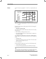
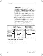
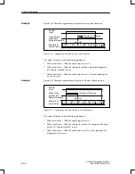
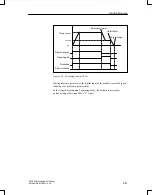
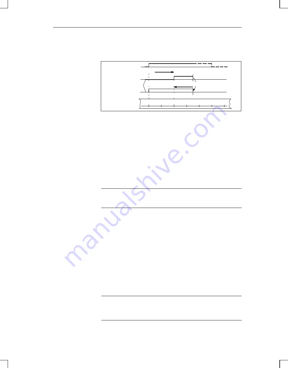
Figure 9-24 illustrates reversal of direction after approaching a setpoint.
1000
2000
3000
4000
5000 6000 7000
Setpoint
Direction of Traverse
Enable
Input
Output, Dia–
gnostics Bit
Setpoint Reached
Example of
Actual Value
Change of Direction
Direction of Traverse
Figure 9-24 Approaching a Setpoint in Up–Count Direction and Subsequent Reversal
of Direction
The actual values have the following significance:
With actual value = 1000, the enable input is set to 1.
With actual value = 3000, the setpoint is reached, the output and the diag-
nostics bit “setpoint reached” are set.
With actual value = 4500, the traversing path is reversed.
With actual value = 1000, the enable input is set to 0, the output and the
diagnostics bit are reset.
Note
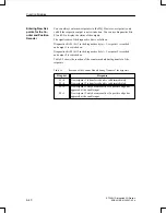
Set outputs can be reset only via a “0” signal to the enable input.
Performance during Overflow
If the counter leaves the counting range of – 32768 to + 32767, then the fol-
lowing occurs:
Bit 3 (overflow) in the diagnostics byte is set to 1.
The outputs of the counter module are disabled.
The enable input (terminal 4 of the terminal block) must be set to 0 to switch
off active outputs.
After an overflow, you need to execute a new reference point approach op-
eration for synchronization of the actual value detection. After reaching the
synchronization, bit 3 in the diagnostics byte is again set to 0, and the outputs
along with the active enable input can be turned on.
Note
During an overflow, active outputs are not switched off, and the SYNC bit
(bit 0 in the diagnostics byte) is not reset.
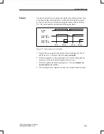
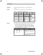
Example
Function Modules


