9-41
ET 200U Distributed I/O Station
EWA 4NEB 812 6087–02b
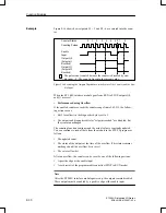
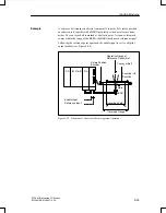
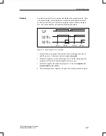
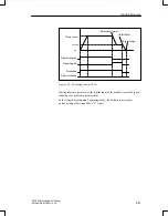
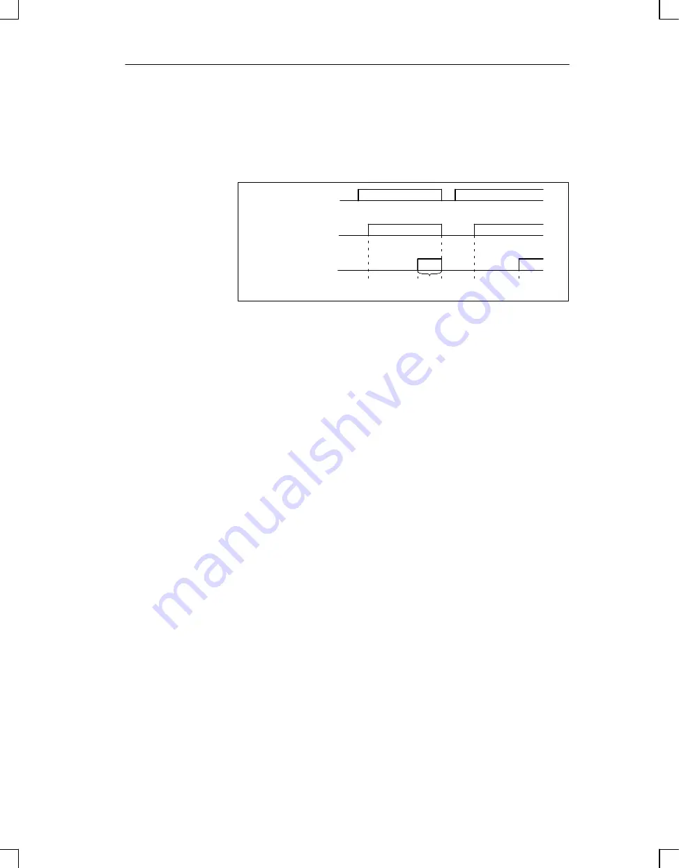
You want to control a drive by using the outputs of the counter module. After
a run of positioning, both setpoints are reached and both outputs are turned
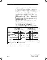
on. You can enter the new setpoints by using the sequence shown in Figure
9-25. The circled numbers are explained following the figure.
S1
Old
S2
Old
S1
New
S2
New
Enable
Input
Output Q0/
Diagn. Bit S1
Output Q1/
Diagn. Bit S2
(1)
(2)
(3)
(4)
(4)
Figure 9-25 Requirement for New Setpoint
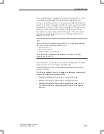
1. Transfer the new setpoints to the module. Since both diagnostic bits S1
and S2 are set to 1, the actual values are not yet accepted.
2. Switch the signal now at the enable input to 0. With the falling edge, the
outputs are switched off and the diagnostics bits are reset.
3. Switch the signal at the enable input again to 1. The new setpoints are
accepted and are now active.
4. After reaching the new setpoints, the respective output is turned on again.
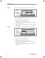
Example
Function Modules

