9-50
ET 200U Distributed I/O Station
EWA 4NEB 812 6087–02b
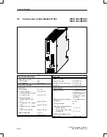
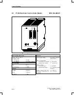
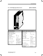
A separate manual is available for the IP 263 positioning module. It can be
ordered under the order number 6ES5 998–5SK11.
The IP 263 is suitable for positioning of two independent axes.
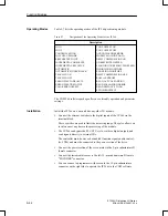
The IP 263 is a two–channel module: 4 digital outputs are assigned to each
channel for the control of drives;
Rapid traverse
Creep speed
Anti–clockwise rotation
Clockwise rotation
Both incremental and absolute encoders (SSI – synchronous serial interface)
can be connected for actual position encoding.
They transmit the machine data, such as
Software limit switches
Resolution
Cutoff difference
Switchover difference
Zero–speed control
The syntax for the data block which has to be created for this purpose is sim-
ple and is described in the manual.
The only thing that remains to be done is to specify the desired target and
then the module is ready for the positioning procedure.
The IP 263 then carries out positioning automatically. When the target has
been reached, it sends a message to the ET 200U interface module and thus
to the CPU.
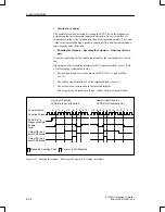
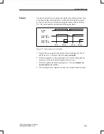
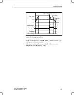
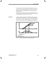
Figure 9-26 shows the positioning procedure with the IP 263: After the start,
a rapid traverse towards the target takes place first. When the switchover/cut-
off point has been reached, a switch–over to creep speed or cutoff takes
place. Afterwards, the IP 263 monitors approach of the target. When the axis
has reached the target range, a signal is sent to the ET 200U interface mo-
dule.
Assignments of
Outputs
Positioning
Function Modules

