9-62
ET 200U Distributed I/O Station
EWA 4NEB 812 6087–02b
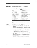
Table 9-7 lists the operating modes of the IP 266 positioning module.
Table 9-7
Designation of the Operating Modes of the IP 266
Description
JOG 1
JOG 2
CONTROLLED JOG
FOLLOW–UP MODE
RREFERENCE POINT
INCREMENTAL ABSOLUTE
INCREMENTAL RELATIVE
AUTOMATIC
AUTOMATIC SINGLE BLOCK
TEACH–IN ON
TEACH–IN OFF
ZERO OFFSET ABSOLUTE
ZERO OFFSET RELATIVE
CLEAR ZERO OFFSET
TOOL OFFSET ON
TOOL OFFSET OFF
ACKNOWLEDGE ERROR
MODIFY MACHINE DATA
DRIFT COMPENSATION ON
UNRESTRICTED SPEED
FLAGGING UNRESTRICTED SPEED
DISABLING MONITORS
ENABLING MONITORS
DRIFT COMPENSATION OFF
RAM
´
EEPROM
READ ACTUAL POSITION
READ FOLLOWING ERROR
READ DISTANCE TO GO
SYNCHRONIZE IP
The COM 266 software package offers user–friendly operation and parameter
settings.
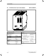
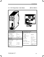
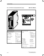
Install the IP 266 on a bus unit like any other I/O module.
Connect the external switches to the digital inputs of the IP 266 via the
terminal block.
These switches are used to limit the traversing range. They also allow you
to intervene at any time in the processing of the module.
The IP 266 can bypass the PLC CPU cycle, via three digital outputs, and
send signals directly to external I/Os.
The controller must, however, be enabled (function signal enable control-
ler, FUM) and must be connected to the power section of the drive.
Connect the power section of the servo motor to the 9–pin subminiature D
female connector.
Connect the incremental sensor to the left 15–pin subminiature D female
“ENCODER” connector.
You can connect a programmer with screen to the 15–pin subminiature
connector on the right side to operate the IP 266 via the COM software.
Operating Modes
Installation
Function Modules


