9-65
ET 200U Distributed I/O Station
EWA 4NEB 812 6087–02b
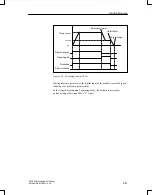
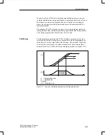
Using a limit switch on the digital inputs, the IP 267 can monitor the limits of
a traversing range and stop the traversing movement when the permissible
range limit is exceeded.
The activated input EXTERNAL STOP causes a calculated deceleration of
the traversing movement.
You can install an emergency limit switch at input IS (pulse inhibit). When
this switch responds, the pulse output is interrupted immediately.
For a reference point approach operation, you can connect an additional
switch at input REF that lies within the traversing zone. The reference point
approach operation is also possible without this switch.
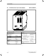
The following table explains the status LEDs of the IP 267
LED
Explanation
RDY
The IP 267 is configured
ACT
Pulse outputs during a positioning operation
ABT
Interruption of the positioning operation
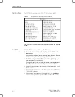
The four operating modes are as follows:
STOP
START FORWARDS
START BACKWARDS
NEUTRAL
Install the IP 267 on a bus unit like any other I/O module.
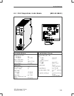
Connect external switches to the DIs of the IP 267 via the terminal block.
Connect the power section of the stepper motor to the 9–pin subminiature
D female connector.
Operation of the IP 267 in the ET 200U distributed I/O system is restricted.
Please note that the acknowledgement for a job can be evaluated only after a
delay time t
d
. This time is calulated as follows:
t
d
= 2
(t
I/O–Bus
+ t
DP
+ t
Prog
)
The delay times t
I/O–Bus
, t
DP
und t
Prog
are explained in the Appendix of the
“ET 200 Distributed I/O System” Manual.
LEDs
Installation
Restriction
Function Modules

