3-4
ET 200U Distributed I/O Station
EWA 4NEB 812 6087–02b
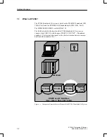
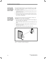
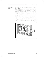
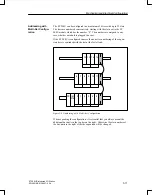
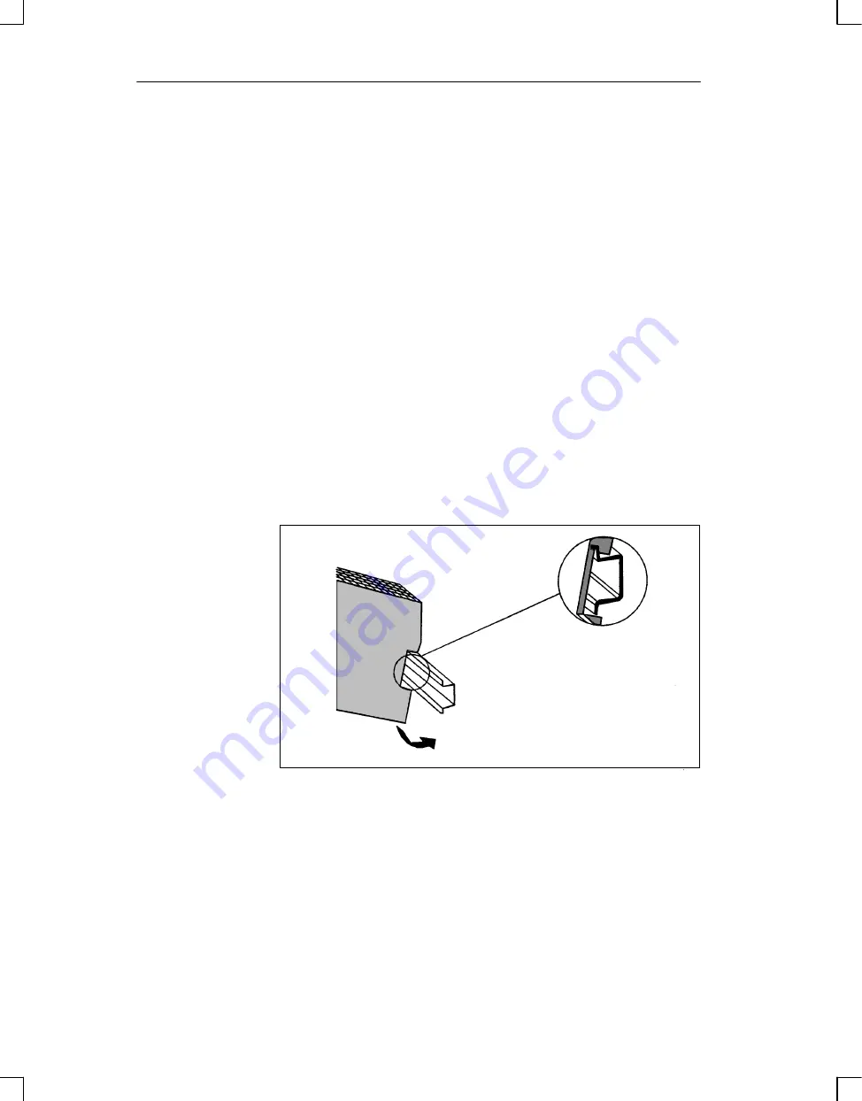
The design of the backplane makes it easy to mount a PS 931 power supply
module and an ET 200U interface module on a standard mounting rail. Pro-
ceed as follows (see Figure 3-1 ):
1. Working from the left end of the standard mounting rail, hang the power
supply module on the rail.
2. Swing the module back until the slide on the module snaps onto the rail.
3. Using the same method, hang an ET 200U interface module onto the rail
next to the power supply module.
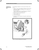
Other than the PS 931, the PS 935 power supply module is located on the
right–hand side of the ET 200U interface module.
1. Connect the ET 200U interface module and the PS 935 power supply mo-
dule via the ribbon cable of the PS 935.
The ET 200U interface module is then located on the left–hand side of the
PS 935.
2. Attach the ET 200U interface module together with the PS 935 onto the
standard mounting rail and
3. Swing both modules back until the slide snaps onto the rail.
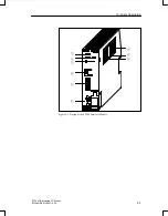
Figure 3-1 Installation on a Standard Mounting Rail
Installing PS 931
Power Supply Mo-
dule and ET 200U
Interface Module
Installing PS 935
Power Supply Mo-
dule and ET 200U
Interface Module
Mechanical and Electrical Configuration

