3-16
ET 200U Distributed I/O Station
EWA 4NEB 812 6087–02b
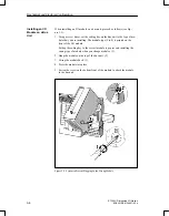
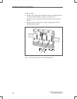
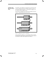
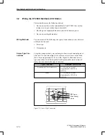
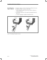
You plug all I/O modules into bus units. You wire the terminal blocks of the
bus units. The information that follows describes connections to screw–type
terminals.
However, you can also use crimp snap–in connections. In both cases, you
will find the terminal assignments on the blocks.
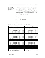
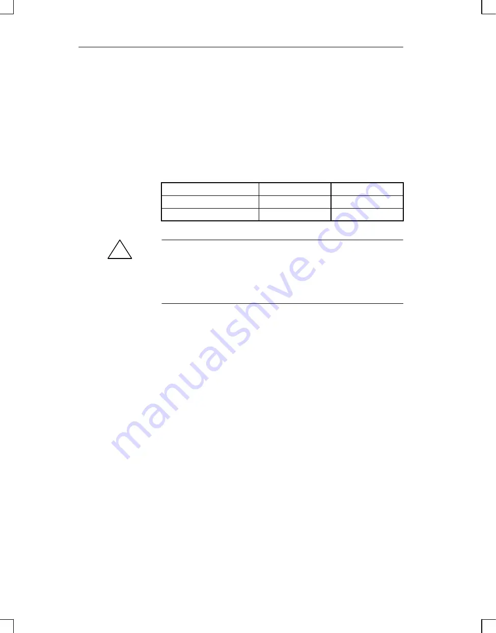
Table 3-2 shows the assignment that always applies when you connect the
load voltage.
Table 3-2
Connecting the Load Voltage to the Terminal Block of a Bus Unit
Load Voltage
Terminal 1
Terminal 2
24 V DC
L+
M
115 V AC/230 V AC
L1
N
!
Caution
After the L+ supply is switched off, energy is stored in digital outputs in an
internal capacitor for about 100 ms.
This energy can be sufficient to activate small loads (e.g. pulse valves) when
an output is triggered.
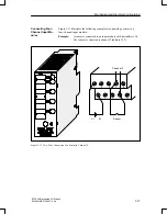
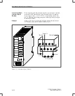
Because all four–channel modules are designed for a two–wire connection,
you can wire directly to a sensor or an actuator without using an external dis-
tribution block.
All 24 V DC four–channel digital modules have a red F LED to indicate
faults. This LED signals a failure of the load voltage. Where inputs are con-
cerned, this LED also indicates a short circuit of M in the sensor lines. Where
outputs are concerned, this LED indicates an output error.
The 115 V AC/230 V AC input modules have no fault LED. The
115 V AC/230 V AC output modules have an LED to indicate a defective
fuse.
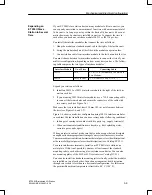
The
four
channels
of
a
module
are
numbered
from
.0
to .3. A pair of ter-
minals on the terminal block is assigned to each channel.
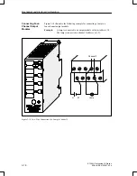
The terminal assignment and the connection diagram are printed on the front
panel of the module.
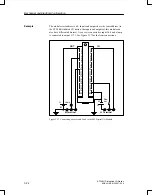
When there is a short in the output circuits, the four–channel output modules
generate a fault signal. You can evaluate this fault signal as a diagnostics sig-
nal via the I/O bus.
Connecting Digital
Modules
Connecting Four–
Channel Digital
Modules
Mechanical and Electrical Configuration

