3-21
ET 200U Distributed I/O Station
EWA 4NEB 812 6087–02b
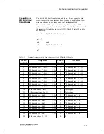
You wire the 482 digital input/output module on a 40–pin connector using
screw–type or crimp snap–in connections. Because the module has no two–
wire connection, you need to use an external distribution block.
One terminal on the 40–pin connector is assigned to each channel. The chan-
nel numbers are printed on the front panel of the module. The 16 channels of
the input side (IN) and the output side (OUT) of the 482 digital I/O module
are numbered.
n + 1.0
Byte “Module A 1”
....
n + 1.7
and
and
n.0
Byte “Module Address”
....
n.7
Table 3-3
Terminal Assignment of the Front Connector of the 482 Digital I/O Module
Connec-
tion (OUT)
Assignment
Connec-
tion (IN)
Assignment
1
L + (for connections 2 to 9)
1
L +
2
“Module a 1” – bit 0
/0.5A
2
“Module a 1” – bit 0
3
“Module a 1” – bit 1
/0.5A
3
“Module a 1” – bit 1
4
“Module a 1” – bit 2
/0.5A
4
“Module a 1” – bit 2
5
“Module a 1” – bit 3
/0.5A
5
“Module a 1” – bit 3
6
“Module a 1” – bit 4
/0.5A
6
“Module a 1” – bit 4
7
“Module a 1” – bit 5
/0.5A
7
“Module a 1” – bit 5
8
“Module a 1” – bit 6
/0.5A
8
“Module a 1” – bit 6
9
“Module a 1” – bit 7
/0.5A
9
“Module a 1” – bit 7
10
M (for connections 2 to 9)
10
Not assigned
11
L+ (for connections 12 to 19)
11
Not assigned
12
“Module address” – bit 0
/0.5A
12
“Module address” – bit 0
13
“Module address” – bit 1
/0.5A
13
“Module address” – bit 1
14
“Module address” – bit 2
/0.5A
14
“Module address” – bit 2
15
“Module address” – bit 3
/0.5A
15
“Module address” – bit 3
16
“Module address” – bit 4
/0.5A
16
“Module address” – bit 4
17
“Module address” – bit 5
/0.5A
17
“Module address” – bit 5
18
“Module address” – bit 6
/0.5A
18
“Module address” – bit 6
19
“Module address” – bit 7
/0.5A
19
“Module address” – bit 7
20
M (for connections 12 to 19)
20
M
Connecting the
482 Digital Input/
Output Module
Mechanical and Electrical Configuration


