3-24
ET 200U Distributed I/O Station
EWA 4NEB 812 6087–02b
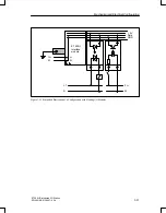
When planning the electrical configuration of your ET 200U distributed I/O
station, note the following:
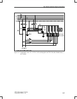
You must provide a main switch (1) for the ET 200U interface module,
the sensors, and the actuators according to VDE 0100.
You can connect the main power for the ET 200U interface module and
the load circuit without providing additional fuse protection (2) if your
radial lines have the following specifications:
–
No more than 3 meters (9.8 ft.) long
–
Inherently ground–fault resistant
–
Inherently short–circuit proof
You need a load power supply (3) for 24 V DC load circuits.
You need a back–up capacitor (rating: 200
F per 1 A load current) for
nonstabilized load power supply units.
If you have AC load circuits with more than five actuating coils, galvanic
isolation by means of a transformer (4) is recommended.
You should ground the load circuit at one end (see Figure 3-19).
Use a low resistance conductor to connect the standard mounting rail to
the cabinet chassis ground (10).
You should fuse the load voltage for sensor and actuator circuits sepa-
rately (6), (7).
A line fuse (9) is necessary to provide protection for the supply voltage.
If the PS 935 power supply module is used, then the ET 200U interface
module and the PS 935 power supply module are connected only via ter-
minal L+ (11). The M line is not provided with the PS 935 module.
Mechanical and Electrical Configuration


