9-11
ET 200U Distributed I/O Station
EWA 4NEB 812 6087–02b
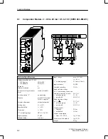
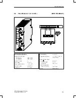
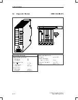
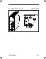
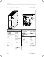
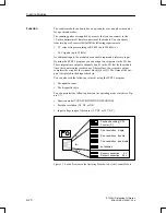
The diagnostic module is used for monitoring the S5–100U I/O bus. The fol-
lowing LEDs on the front panel display the signal states of the control lines
and the supply voltage for the I/O bus:
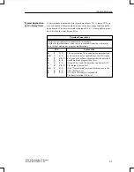
IDENT
The programmable controller executes an IDENT run after each change from
STOP to RUN mode and after any changes in the configuration in order to
determine the current configuration of the programmable controller. The
IDENT LED lights up briefly.
If the LED lights up in the RUN mode, this indicates that a faulty I/O module
has been plugged in.
CLEAR
The CLEAR signal line is 1 only in the STOP mode in normal operation.
In this case, the outputs of the output modules are disabled.
If CLEAR is 1 in the RUN mode, the control line itself may be defective (no
contact).
LATCH/CLOCK
These two control lines control data interchange between the ET 200U inter-
face module, the I/O bus, and the I/O modules.
During normal operation, both LEDs must flash.
The flashing frequency provides information on the speed of the serial bus.
If both LEDs show a steady light in the RUN mode, the bus unit that the
diagnostic module is plugged into is defective.
DATA/DATA–N
The alternate lighting up of the DATA and DATA–N LEDs indicates data
flow on the I/O bus.
If these two LEDs show a steady light, the bus unit that the diagnostic mo-
dule is plugged into is defective.
U1
v
8 V
If the supply voltage of a slot remains at a value U1
v
8 V, proper functioning
of the I/O modules is no longer guaranteed. An excessively high bus load
(> 1 A) causes the low supply voltage.
If this LED flickers, noise pulses are superimposed on the supply voltage U1
(e.g., by the coupling of noise pulses).
The LED lights up briefly if the programmable controller is switched on or
off.
U1 > 8 V
The supply voltage of the I/O bus is O.K.
Function
Function Modules

