9-15
ET 200U Distributed I/O Station
EWA 4NEB 812 6087–02b
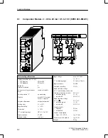
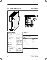
The module consists of two independent down counters with isolated inputs
and outputs. It counts input signals up to a frequency of 500 Hz from a set
value down to the value 0. When zero is reached, the 24 V DC output of the
module is energized.
At
the
same
time, a green LED on the module lights up and the input signal
(I x.0 or I x.1) is set to 1.
You can enter the setpoint (0 to 999) via the three–digit thumbwheel switches
on the front panel of the module.
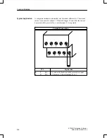
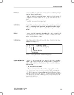
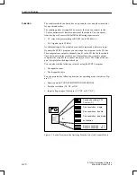
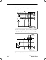
You can set the input voltage ranges for 5 V DC or 24 V DC on rocker
switches on the front panel (see Figure 9-4).
Channel 0
Channel 1
Channel 1
Channel 0
24 V DC
5 V DC (TTL)
Figure 9-4 Setting the Input Voltage Range on the Counter Module (500 Hz)
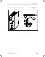
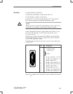
You install the counter module on a bus unit like any other module.
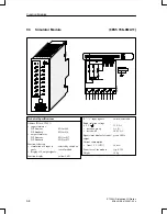
See the schematic diagram.
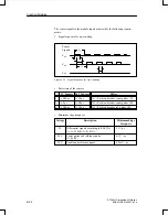
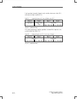
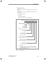
You can address a counter module like a two–channel digital module (chan-
nel 0 or 1). For enabling and resetting the counter, you address the module
like a digital output module. The counter reading is scanned in the same way
as a digital input module (see Figure 9-5).
Function
Installation
Wiring
Addressing
Function Modules

