9-21
ET 200U Distributed I/O Station
EWA 4NEB 812 6087–02b
Installing and Removing the Module
You install the counter module on a bus unit like other I/Os.
Set the coding key to number 6 on the bus unit.
Disconnect the 24 V DC power supply (terminals 1 and 2 of the terminal
block) before connecting or disconnecting the transducer cables.
!
Caution
Damage to sensor. Can cause minor property damage. Do not connect or di-
sconnect the 5 V DC transducer cable while the module is energized.
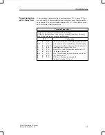
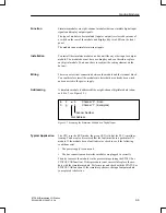
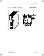
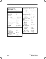
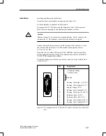
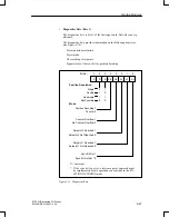
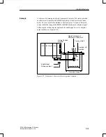
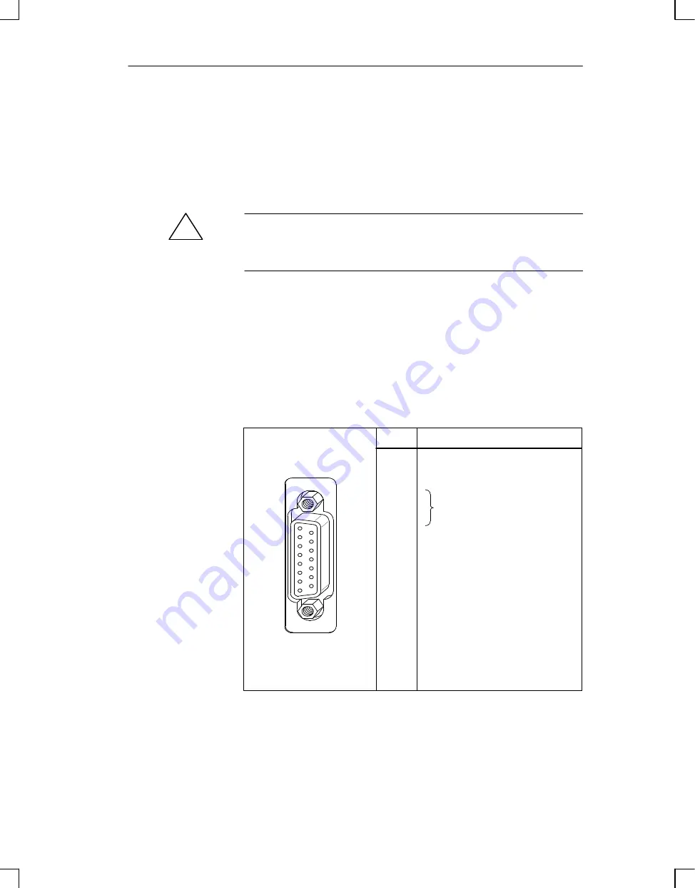
Connect pulse and position sensors on the front panel by means of a 15–pin
sub–D connector (see Figure 9-8). The module can supply the sensors
(5 V DC or 24 V DC).
Basically, you can connect all sensors if they fulfill the requirements of the
system signals and supply voltage. You cannot connect sensors with OPEN–
COLLECTOR outputs to the module.
The shield connection of the sensors must be connected to the metallic front
connector cover.
1
2
3
4
5
6
7
8
9
10
11
12
13
14
15
5 V Supply Voltage
5 V Sensor Line
Ground
Rectang. Wave Sign. A–N (5 V)
Rectang. Wave Signal A (5 V)
Supply Voltage (24 V)
Rectang. Wave Signal B (5 V)
Rectang. Wave Sign. B–N (5 V)
Reference Pulse R (5 V)
Reference Pulse R–N (5 V)
Rectang. Wave Signal A (24 V)
Rectang. Wave Signal B (24 V)
Reference Pulse R (24 V)
Pin
Assignment
Figure 9-8 Pin Assignment of the 15–Pin Sub–D Female Connector of the Counter Mo-
dule
Installation
Function Modules

