9-31
ET 200U Distributed I/O Station
EWA 4NEB 812 6087–02b
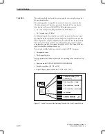
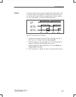
In the operation mode POSITION DECODING, the module works as an up–
counter/down–counter and counts the pulses of the connected position en-
coder. Based on the phase offset of the two decoder signals A and B, the
counter determines the counting direction. If the counter reaches a prese-
lected setpoint, the respective output is then turned on.
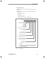
Set the following items on the operating mode switch:
POSITION DECODING (PD) function
The desired position resolution (single, double, or quadruple)
The signal level of the counting pulses (5 V or 24 V)
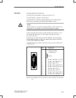
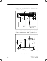
Connect the sub–D interface female connector to an incremental position
encoder that has to deliver the following signals:
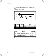
Two counting pulses offset by 90 degrees
A reference pulse
The pulses can be supplied as 5 V differential signals according to RS 422
(up to 500 kHz) or as 24 V DC signals (up to 25 kHz).
Connect a switch to the enable input. This switch must deliver a 24 V signal.
In the same way, the reference pulse has to deliver a 24 V signal to the refer-
ence input.
Position Resolution:
Counter capacity
The 16–bit up/down counter permits a resolution of 65,536 units between
– 32768 and +32767. The traversing range depends on the resolution of
the position encoders.
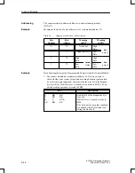
Pulse evaluation
The counting pulses, which are offset by 90 degrees, can be subjected to
single, double, or quadruple evaluation. The necessary setting is made on
the operating mode switch (see Figure 9-7).
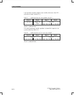
The accuracy of the traversing path increases accordingly if double or
quadruple pulse evaluation is used.
However,
the
traversing range then
available is reduced by a factor of 2 or 4 (see Table 9-3).
Functional Des-
cription of the Po-
sition Decoder
Settings
Function Modules


