9-46
ET 200U Distributed I/O Station
EWA 4NEB 812 6087–02b
The module is well–suited to take over control–loop tasks in the area of indu-
strial processing technology such as temperature control, pressure and flow
control, continuous injection functions, and non–time–critical closed–loop
speed controls.
The module relieves the programmable controller from closed–loop control
tasks. The IP 262 also works with its own power supply in a stand–alone op-
eration. The module can function independently without a programmable
controller and can handle up to four closed–loop control circuits.
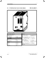
The following two interfaces are located on the front panel of the module:
An interface for connecting a programmer (PG), an operator panel (OP),
or the SINEC L1 Network (under development)
An interface for connecting analog and binary inputs
In addition, the following items are available:
A selector switch for each channel for current and voltage (thermocouples
or PT 100)
A green status LED with the following indications:
–
Continuously lit, to signify the RUN mode
–
Flashing, to signify a transducer malfunction
–
Off, to signify a transducer malfunction
Additionally, the module offers the following inputs:
Four analog inputs for direct feed of setpoint and actual values
Four binary inputs for control variables
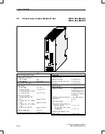
There are two IP 262 modules as follows:
...–8MA12 with 3 analog outputs for continuous controllers with analog
output signals.
...–8MB12 with 8 binary outputs for continuous controllers with pulse
time interval signals or for step–action controllers.
For this purpose, you can order a separate manual for working with this mo-
dule (see Catalog).
Install the closed–loop control module on a bus unit like any other input or
output module.
The connections for power supply and the analog and binary output sig-
nals are located on the terminal block of the bus unit.
The analog and binary inputs are connected to the module with a 25–pin
sub–D female connector.
Function
Modules
Installation
Function Modules


