3-15
ET 200U Distributed I/O Station
EWA 4NEB 812 6087–02b
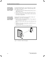
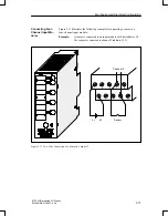
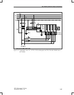
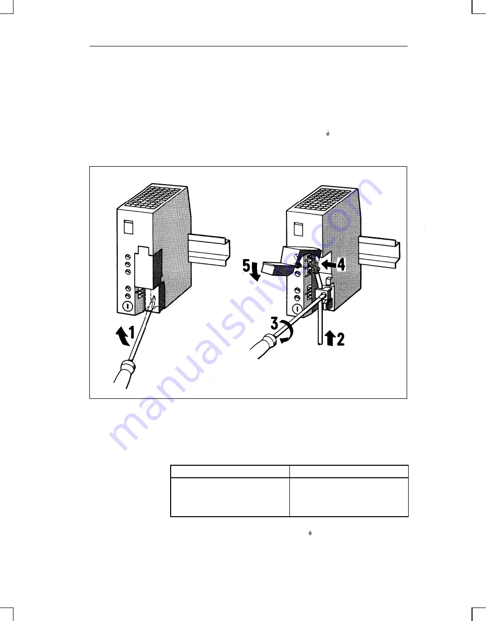
To connect a PS 931 power supply module to the main power, proceed as
follows (see Figure 3-12):
1. Set the voltage selector to the line voltage that you are using.
2. Lift the protective cover. (1)
3. Connect the power cable to terminals L1, N and (2), (3), (4) and
4. Close the protective cover. (5)
Figure 3-12 Connecting a Power Supply Module to the Mains
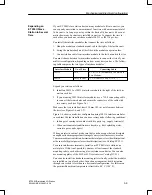
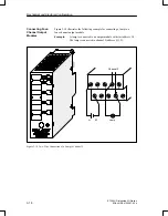
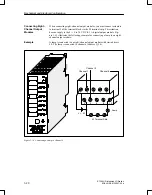
Connection of the ET 200U interface module to a power supply module is
different for the PS 931 and PS 935.
PS 931
PS 935
1. Connect the L+ and M terminals
of the PS 931 power supply mo-
dule to the correspond. terminals
on the ET 200U interf. module.
1. Connect the L+ terminal of the
PS 935 power supply module to
the correspond. terminals on the
ET 200U interf. module.
2. For a grounded configuration, connect the terminal of the ET 200U in-
terface module to the standard mounting rail.
Connecting a
PS 931 or PS 935
Power Supply Mo-
dule to the Main
Power
Connecting an ET
200U Interface Mo-
dule to a PS 931 or
PS 935 Power Sup-
ply Module
Mechanical and Electrical Configuration

