3-23
ET 200U Distributed I/O Station
EWA 4NEB 812 6087–02b
3.3
Electrical Configuration of the ET 200U Distributed I/O Station
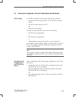
The ET 200U distributed I/O station has the following electrical circuits:
The control circuit for logic control (24 V DC for the ET 200U interface
module)
The control circuit for sensors (24 V DC)
and
The load circuit for actuators.
To supply the control and load circuits, use one of the following:
The PS 931 power supply module
or
The PS 935 power supply module
or
A Siemens load power supply of the 6EV1 series (see Catalog ET1).
If you connect any other load power supply, the voltage must be in a range of
20 V to 30 V (including ripple) and the load power supply must be safely
isolated to DIN VDE 0160.
Note
If you use switch–mode power supply units to supply floating analog modu-
les and BERO poximity limit switches, you must first run this supply through
a line filter.
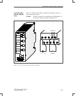
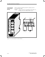
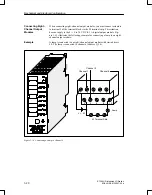
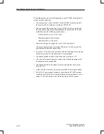
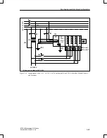
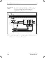
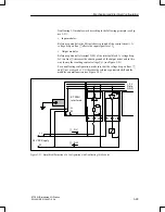
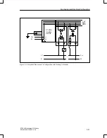
Figures 3-18 through 3-20 show the following configurations for an ET 200U
slave station:
Configuration with a 115 V AC/230 V AC power supply for an ET 200U
interface module, sensors, and actuators
Grounded configuration with a 24 V DC power supply for an ET 200U
interface module, sensors, and actuators
and
Ungrounded configuration with a 24 V DC power supply for an ET 200U
interface module.
Power Supply
General Electrical
Configuration of
an ET 200U Slave
Station
Mechanical and Electrical Configuration

