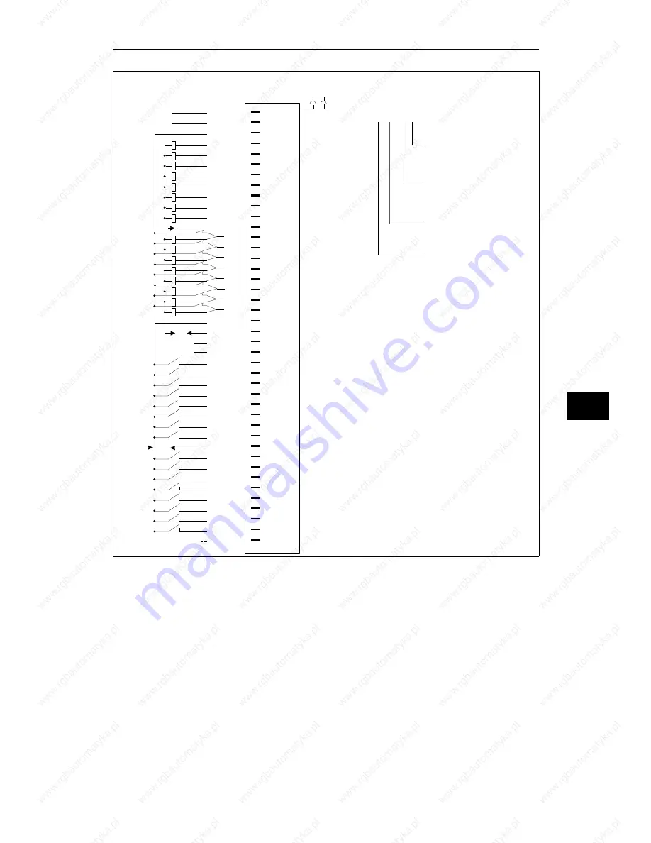
SYSNIN, SYNOUT only relevant for operation with the IP 257
F+/F- =
Enable input
1) Changeover of enable mode with jumper X20:
Jumper inserted = Enable input active (factory setting)
Jumper open = Enable input inactive.
Switch S2 must be at setting 1.
1Q0.0
1Q0.1
1Q0.3
1Q0.4
1Q0.5
1Q0.6
1Q0.7
1Q0.2
1Q1.0
1Q1.1
1Q1.2
1Q1.3
1Q1.4
1Q1.5
1Q1.6
1Q1.7
SYN IN
SYN OUT
1I2.0
1I2.1
1I2.2
1I2.3
1I2.4
1I2.5
1I2.6
1I2.7
1I3.0
1I3.1
1I3.2
1I3.3
1I3.4
1I3.5
1I3.6
1I3.7
F+
1
2
3
4
5
6
7
8
9
10
11
12
13
14
15
16
17
18
19
20
21
22
23
24
25
26
27
28
29
30
31
32
33
34
35
36
37
38
39
40
41
42
Pin
L+
L+
H+
F-
L-
L-
L-
Connection of
Process Signal
Lines
1)
x20
Example of connection designation for
an output:
(1) Q 1.6
Input 6 (6th bit);
0 to 7 possible
Address of output byte
(1st byte);
0 to 255 possible
Q = Output
I = Input
1st terminal L+
(not specified in the
address)
8
Specification Sheets for the Modules
System Manual
C79000-B8576-C199-03
8 - 73


