Application planning
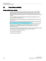
4.3 Power balance calculation
Automation system
106
System Manual, 12/2017, A5E03461182-AE
Causes for overload
An overload can still occur despite a positive power balance during planning. The cause for
overload can be a hardware configuration that does not correspond to the configuration in
STEP 7, for example:
●
More I/O modules are inserted in the actual configuration than were planned.
●
A supply voltage L+ (24 V DC) that is necessary for operation is not connected when
system voltage infeed via the CPU/interface module is specified during parameter
assignment (see section Special considerations for the use of a system power supply in
the first power segment (Page 99)).
●
A system power supply that is necessary for operation is not inserted.
●
A system power supply that is necessary for operation is not switched on (power
connection plug or on/off switch).
●
A system power supply that is necessary for operation has no U connector inserted.
Response of the CPU to negative power balance or failure of system power supplies
As soon as the CPU detects a negative power balance/overload, the following actions are
executed:
●
The CPU stores the retentive data.
●
The CPU enters the event in the diagnostics buffer.
●
The CPU carries out a restart and repeats this until the cause of the negative power
balance is resolved.
Response of the interface module to negative power balance or failure of system power supplies
As a result of the overload, the interface module switches off all power segments. The I/O
controller or DP master can no longer access the I/O modules. The interface module
provides diagnostic information and periodically checks the connection to the backplane bus
and re-establishes it.
Exception: In the case of a voltage drop or a hardware fault in power segment 2 or 3, the
corresponding system power supply module switches off its power segment (and possibly
the following segments), and generates a diagnostic alarm, if possible.
More information on the behavior of the system power supply (PS) in the event of a fault can
be found in the manuals for the system power supplies.
Summary of Contents for Simatic S7-1500/ET 200MP
Page 1: ......


