Wiring
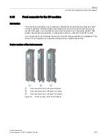
6.10 Front connector for the I/O modules
Automation system
System Manual, 12/2017, A5E03461182-AE
153
7.
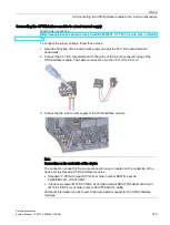
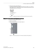
Wire the power supply element (Figure 8).
Terminals 41/42 and 43/44 are galvanically connected to each other. If you connect the
supply voltage to 41 (L+) and 44 (M), you can then loop-through the potential to the next
module with terminals 42 (L+) and 43 (M).
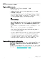
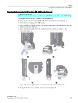
Figure 6-13 Preparing front connectors for I/O modules with shield connection element (3)
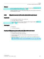
Wiring front connectors for I/O modules with shield contact element
To wire a front connector, follow these steps:
1.
Strip the cable shielding.
2.
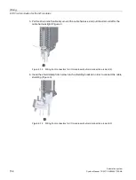
Begin to completely wire the front connector (Figure 1).
Figure 6-14 Wiring front connectors for I/O modules with shield connection element (1)
Summary of Contents for Simatic S7-1500/ET 200MP
Page 1: ......


