System overview
3.9 Power supply
Automation system
System Manual, 12/2017, A5E03461182-AE
83
Configuration example of a system with load power supply and system power supply
The following figure shows a system configuration with load power supply and additional
system power supply.
Figure 3-22 Overall configuration of power supply
In order to ensure the supply of the modules from the backplane bus, the incoming power is
compared with the required power in the TIA Portal engineering system or in the TIA
Selection Tool.
As early as in the planning stages, make sure that the power fed into the backplane bus is
always greater than or equivalent to the power drawn.
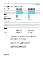
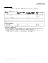
System power supply modules
System power supplies supply the internal electronics of the S7-1500 modules with power
via the backplane bus. The table below shows the available system power supply modules:
Short designation PS 25W 24V DC
PS 60W 24/48/60V DC
PS 60W
24/48/60V DC HF
PS 60W 120/230V
AC/DC
Article number
Manual
Rated input volt-
age
24 V DC
24 V DC, 48 V DC, 60 V
DC
24 V DC, 48 V DC,
60 V DC
120 V AC, 230 V AC
120 V DC, 230 V DC
Output power
25 W
60 W
60 W
60 W
Electrical isolation
from the back-
plane bus
X
X
X
X
Diagnostic inter-
rupt
X
X
X
X
Energy buffering
for data backup in
the CPU
---
---
up to 20 MB reten-
tive
---
Summary of Contents for Simatic S7-1500/ET 200MP
Page 1: ......


