Installation
5.1 Basics
Automation system
System Manual, 12/2017, A5E03461182-AE
109
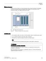
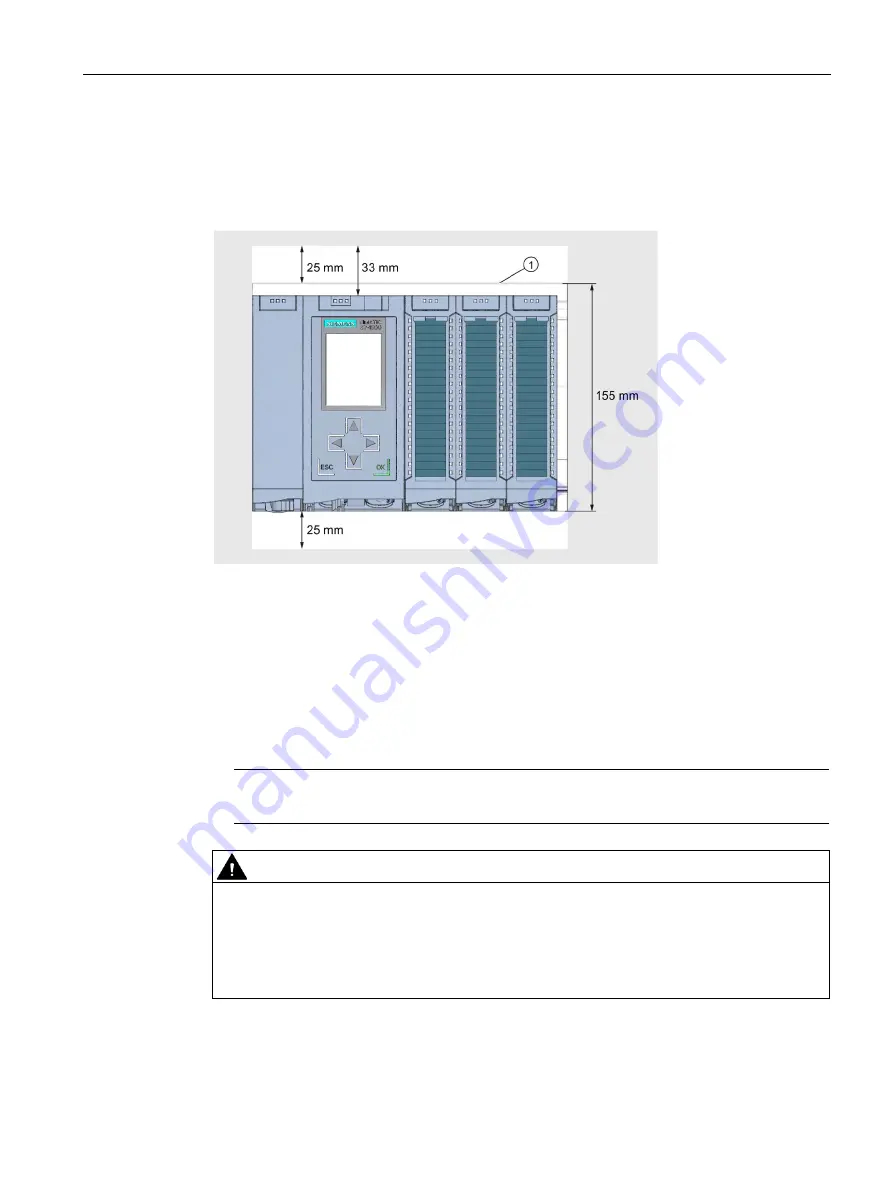
Minimum clearances
Modules can be mounted up to the outer edge of the mounting rail. Maintain the following
minimum clearances at the top and bottom when installing or removing the S7-1500
automation system / ET 200MP distributed I/O system:
①
Upper edge of the mounting rail
Figure 5-1
Minimum clearances in the control cabinet
Installation rules
●
The installation starts on the left with a CPU/interface module or a system power supply.
●
You connect the modules to each other with U connectors.
●
Note that no U connector protrudes from the first and last module.
Note
Only remove and insert modules when the power to the system is switched off.
WARNING
Protection from conductive contamination
Taking into consideration the ambient conditions, you must protect the devices from
conductive contamination.
This can be achieved, for example, by installing the devices in a control cabinet with the
appropriate degree of protection.
Summary of Contents for Simatic S7-1500/ET 200MP
Page 1: ......


