Wiring
6.5 Wiring rules
Automation system
134
System Manual, 12/2017, A5E03461182-AE
6.5
Wiring rules
Introduction
Use suitable cables for connecting the S7-1500 automation system/ET 200MP distributed
I/O system. The following tables present the wiring rules for the CPU, interface module,
system power supply, load current supply, front connector and power supply elements.
CPU, interface module, system power supply and load current supply
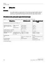
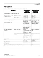
Table 6- 2
Wiring rules for CPU, interface module, system power supply and load current supply
Wiring rules for ...
CPU/interface module
System power and load current
supply
Permitted cable cross-sections of solid cables (Cu)
-
-
-
-
Permitted cable cross-
sections of flexible cables
(Cu)
Without wire end
sleeve
0.25 to 2.5 mm
2
1.5 mm
2
AWG
*
: 24 to 16
AWG
*
: 16
With end sleeve
0.25 to 1.5 mm
2
1.5 mm
2
AWG
*
: 24 to 16
AWG
*
: 16
Number of wires per connection
1
1
Stripped length of the wires
10 to 11 mm
7 to 8 mm
End sleeves according to
DIN 46228
without plastic sleeve Design A, 10 mm long
Design A, 7 mm long
with plastic sleeve 0.25
to 1.5 mm
2
Design E, 10 mm long
Design A, 7 mm long
Sheath diameter
-
8.5 mm
Tool
3 to 3.5 mm screwdriver, conic
design
3 to 3.5 mm screwdriver, conic
design
Connection system
Push-in terminal
Screw terminal
Tightening torque
-
from 0.5 Nm to 0.6 Nm
* American Wire Gauge
Summary of Contents for Simatic S7-1500/ET 200MP
Page 1: ......


