Wiring
5.9 Connecting interfaces for communication with S7-1500H
S7-1500R/H redundant system
System Manual, 10/2018, A5E41814787-AA
127
Cabling
Necessary components
Specifications
Installation cable for indoor use
also
•
1 cable with 4 cores per S7-1500H system
Both interfaces in one cable
•
1 or 2 cables with multiple shared cores
Interfaces laid separately to increase availability (reduc-
tion of common cause factor)
•
Connector type ST or SC, for example, in line with the
other components
See also other specifications applicable to your plant:
•
UL approval
•
Halogen-free
Avoid splicing cables in the field.
Use the pre-assembled cables with pulling protection/aids in
whiplash or breakout design, including measuring log.
Patch cable for indoors
Connector type LC on ST or SC, for example, in line with
the other components.
Installation through distri-
bution boxes
A cable junction is re-
quired between the indoor
and outdoor area.
Additional information can
be found in the section
below.
•
One distribution box/junction
box for each branch.
•
Connecting the installation
and patch cables via the
distribution box. Use either
ST or SC plug-in connect-
ors.
Connector type ST or SC, for example, in line with the other
components.
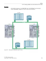
Installation of fiber-optic cable through distribution boxes
①
H-CPU (CPU 1517H-3 PN)
②
Additional distribution boxes, if necessary, for example with SC or ST couplers. This allows you
to combine individual sections to achieve the required total length (maximum of 10 km) of fiber-
optic cable.
③
Patch cable (duplex), for example LC-SC/ST
④
Distribution box, for example with SC or ST couplers
Figure 5-9
Fiber-optic cables, installation through distribution boxes
Summary of Contents for Simatic S7-1500H
Page 1: ......


