Index-6
S7-200 Programmable Controller, CPU 210
C79000-G7076-C235-01
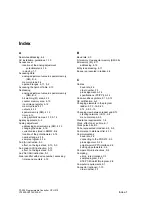
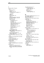
L
LAD.
See Ladder or Program
Ladder
basic elements, 4-9
boxes, 4-9
changing to STL, 2-9
changing elements in a program, 2-7,
3-16–3-20
coils, 4-9
contacts, 4-9
displaying status, 2-16
editor, 2-7
entering a program, 2-7, 3-15–3-20
inserting an instruction, 3-16–3-20
networks, 2-7, 4-9
program examples
contact instructions, 5-4
counter, 5-8
End (MEND), 5-12
high-speed counter, 4-14–4-16, 5-16
increment/decrement word, 5-9
interrupt, 4-14–4-16, 5-16
jump to label, 5-12
logic stack (ALD and OLD), 5-13
move word, 5-10
output instructions, 5-5
timer, 5-7
watchdog reset, 5-12
sample program, 3-1–3-25
sharing data between main program and
interrupt, 5-15
tools of the Ladder Editor, 3-15
using the Ladder Editor, 2-7, 3-15–3-20
viewing a program, 2-9
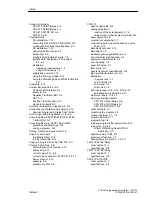
Last scan time, stored in special memory (SM),
B-2
Load (LD) / Load Not (LDN), effect on the logic
stack, 5-3
Load (LD) instruction, 5-3
effect on the logic stack, 4-10
Load Not (LDN) instruction, 5-3
Loading a program
CPU 210, 2-11
PDS 210, 2-10–2-12
Location of the analog adjustment potentiometer,
4-16
Logic stack, 4-10
affected by the interrupt routine, 5-15
effect of Or (O) / And (A) / Load (LD), 4-10
effect of Or Load (OLD) / And Load (ALD),
5-13
Logic Stack instructions, 5-13
And Load (ALD), 5-13
effect on logic stack, 5-13
example, 5-13–5-15
operation, 5-13
Or Load (OLD), 5-13
effect on logic stack, 5-13
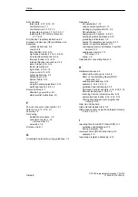
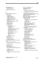
M
Main Program End (MEND) instruction, 4-5, 5-11
Main program segment, 4-5
Manuals, order number, F-1
Maximum scan time, stored in special memory
(SM), B-2
Memory areas, 4-4
accessing data, 4-11
addressing bit memory (M), 4-12
addressing special memory (SM), 4-12
addressing the inputs, 4-12
addressing the outputs, 4-12
bit memory (M), 4-11
CPU 210, 4-11–4-13
PDS 210, 4-11–4-13
saved in the CPU 210, 2-12
Memory cartridge
copying a program from the PDS 210, 2-11
location
CPU 210 AC/AC/Relay, A-9
CPU 210 AC/DC/Relay, A-7
CPU 210 DC/DC/DC, A-5
PDS 210, A-11
order number, F-1
power up with an empty memory cartridge,
2-12
scan cycle, 4-6–4-8
specifications, A-12, A-13
transporting the program to the CPU 210,
2-10–2-12
MEND instruction, 5-11
Menu of editing functions, right mouse button
Status Chart, 2-15
Symbol Table, 2-14
Minimum scan time, stored in special memory
(SM), B-2
Monitoring
program, 2-16
sample program, 3-23
Index
Summary of Contents for Simatic S7-200 CPU 210
Page 10: ...x S7 200 Programmable Controller CPU 210 C79000 G7076 C235 01 Contents ...
Page 116: ...A 16 S7 200 Programmable Controller CPU 210 C79000 G7076 C235 01 CPU 210 Data Sheets ...
Page 126: ...F 2 S7 200 Programmable Controller CPU 210 C79000 G7076 C235 01 CPU 210 Order Numbers ...
Page 138: ...Index 12 S7 200 Programmable Controller CPU 210 C79000 G7076 C235 01 Index ...

