1-6
S7-200 Programmable Controller, CPU 210
C79000-G7076-C235-01
1.3
Installing a CPU 210
Warning
Failure to disable all power to the CPU 210 and related equipment during installation or
removal procedures may result in death or serious personal injury, and/or damage to
equipment.
Disable all power to the CPU 210 and related equipment before installation or removal.
Always follow appropriate safety precautions and ensure that power to the CPU 210 is
disabled before installation.
Mounting a CPU 210 on a Panel
To install a CPU 210 on a panel, follow these steps:
1. Locate, drill, and tap the mounting holes for DIN M4 or American Standard number 8
screws. Refer to Section 1.2 for mounting dimensions and other considerations.
2. Secure the CPU 210 onto the panel, using DIN M4 or American Standard number 8
screws.
Installing a CPU 210 on a DIN Rail
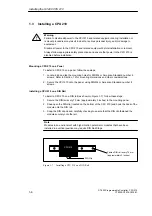
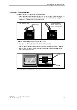
To install a CPU 210 on a DIN rail (as shown in Figure 1-7), follow these steps:
1. Secure the DIN rail every 75 mm (approximately 3 inches) to the mounting panel.
2. Snap open the DIN clip (located on the bottom of the CPU 210) and hook the back of the
module onto the DIN rail.
3. Snap the DIN clip closed, carefully checking to ensure that the DIN clip fastened the
module securely onto the rail.
Note
Modules in an environment with high vibration potential or modules that have been
installed in a vertical position may require DIN Rail Stops.
CPU 210
DIN Clip
Fasten DIN rail every 75 mm
(approximately 3 inches)
Figure 1-7
Installing a CPU 210 on a DIN Rail
Installing the S7-200 CPU 210
!
Summary of Contents for Simatic S7-200 CPU 210
Page 10: ...x S7 200 Programmable Controller CPU 210 C79000 G7076 C235 01 Contents ...
Page 116: ...A 16 S7 200 Programmable Controller CPU 210 C79000 G7076 C235 01 CPU 210 Data Sheets ...
Page 126: ...F 2 S7 200 Programmable Controller CPU 210 C79000 G7076 C235 01 CPU 210 Order Numbers ...
Page 138: ...Index 12 S7 200 Programmable Controller CPU 210 C79000 G7076 C235 01 Index ...

