1-7
S7-200 Programmable Controller, CPU 210
C79000-G7076-C235-01
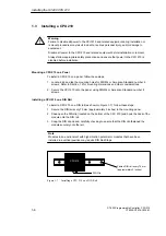
Installing a CPU 210 in a Panel Box
To install a CPU 210 in a panel box, follow these steps:
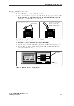
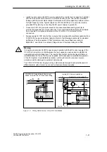
1. Open one of the I/O access covers on the CPU 210. As shown in Figure 1-8, remove the
access cover by gently pressing against the access cover until the hinges spring free.
Repeat this procedure for the other access cover.
Open the access cover.
Gently press against the
access cover until the
access cover snaps off.
Access covers
CPU 210
(Side View)
CPU 210
(Side View)
CPU 210
(Side View)
CPU 210
(Side View)
Figure 1-8
Removing the Access Covers from the CPU 210
2. Snap open the DIN clip (located on the bottom of the module).
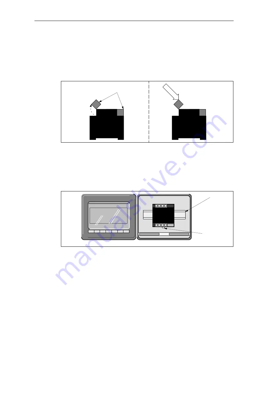
3. Open the panel box and hook the back of the module onto the DIN rail. See Figure 1-9.
4. Snap the DIN clip closed, carefully checking to ensure that the DIN clip fastened the
module securely onto the rail.
CPU 210
DIN Clip
DIN rail
Figure 1-9
Installing the CPU 210 in a Panel Box
Installing the S7-200 CPU 210
Summary of Contents for Simatic S7-200 CPU 210
Page 10: ...x S7 200 Programmable Controller CPU 210 C79000 G7076 C235 01 Contents ...
Page 116: ...A 16 S7 200 Programmable Controller CPU 210 C79000 G7076 C235 01 CPU 210 Data Sheets ...
Page 126: ...F 2 S7 200 Programmable Controller CPU 210 C79000 G7076 C235 01 CPU 210 Order Numbers ...
Page 138: ...Index 12 S7 200 Programmable Controller CPU 210 C79000 G7076 C235 01 Index ...

