background image

3-1

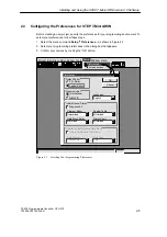
S7-200 Programmable Controller, CPU 210
C79000-G7076-C235-01

Getting Started with a Sample Program

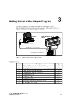
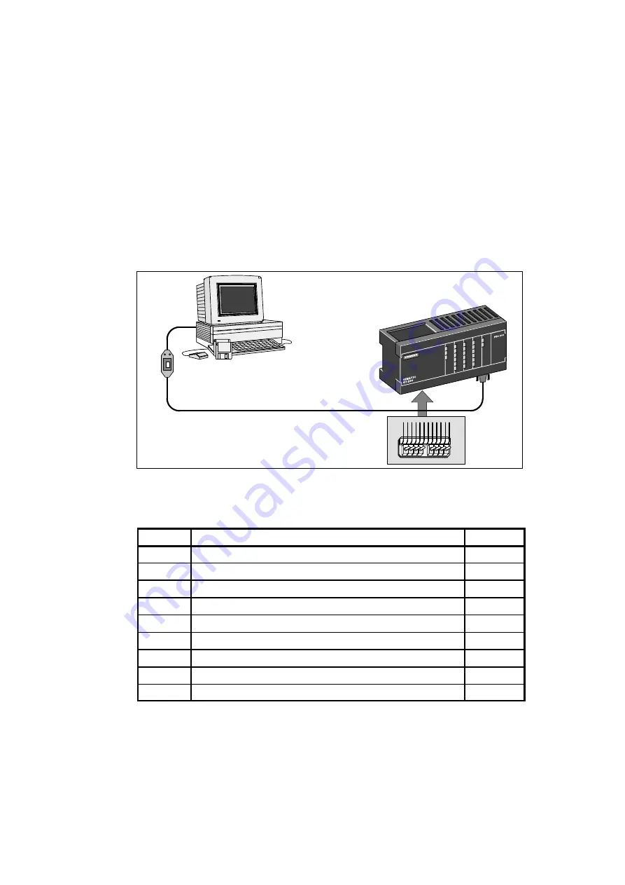
You can enter the program for the sample application on a computer running
STEP 7-Micro/WIN. To download the program, you must have the equipment shown in
Figure 3-1. The size of the sample program is 155 bytes.

Input Simulator for the PDS 210

Program Development Station
(PDS 210)

PC/PPI Communications Cable

Computer

STEP 7-Micro/WIN

Figure 3-1

Requirements to Run the Sample Program

Chapter Overview

Section

Description

Page

3.1

Defining the Requirements for the Application Example

3-2

3.2

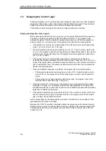
Designing the Control Logic

3-4

3.3

Putting the Control Logic into a Program

3-9

3.4

Creating a Project with STEP 7-Micro/WIN

3-13

3.5

Creating a Symbol Table

3-14

3.6

Creating the Program

3-15

3.7

Creating a Status Chart

3-22

3.8

Downloading and Monitoring the Sample Program

3-23

3.9

Modifying the Sample Program

3-25


3

Summary of Contents for Simatic S7-200 CPU 210

Page 1: ... Concepts for Programming the CPU 210 4 Instruction Set 5 Appendix CPU 210 Data Sheets A Special Memory SM B Error Handling and Error Codes C Converting STEP 7 Micro DOS Files to STEP 7 Micro WIN Files D Execution Times for STL Instructions E CPU 210 Order Numbers F Index C79000 G7076 C235 01 S7 200 Programmable Controller CPU 210 System Manual SIMATIC ...

Page 2: ...applicationsdescribedinthecatalogorthetechnical description and only in connection with devices or components from other manufacturers which have been approved or recommended by Siemens Thisproductcanonlyfunctioncorrectlyandsafelyifitistransported stored setup andinstalledcorrectly and operated and maintained as recommended SIMATICR and SINECR are registered trademarks of SIEMENS AG Third parties ...

Page 3: ...tion contained in this manual pertains in particular to the following products S CPU 210 and the PDS 210 S STEP 7 Micro WIN version 2 0 programming software How to Use This Manual If you are a first time novice user of S7 200 Micro PLCs you should read the entire manual If you are an experienced user refer to the table of contents or index to find specific information The manual is organized in th...

Page 4: ...ion such as the equipment data sheets error code descriptions and execution times are provided in the appendices Additional Assistance For assistance in answering technical questions for training on this product or for ordering contact your Siemens distributor or sales office Preface ...

Page 5: ...uits 1 9 Using the Optional Field Wiring Connector 1 10 Guidelines for AC Installation 1 10 Guidelines for DC Installation 1 10 1 5 Using Suppression Circuits 1 12 Protecting DC Transistors 1 12 Protecting Relays Controlling DC Power 1 12 2 Installing and Using the STEP 7 Micro WIN Version 2 0 Software 2 1 Installing the STEP 7 Micro WIN Version 2 0 Software 2 2 Pre installation Instructions 2 2 I...

Page 6: ...Status of the Program in Ladder Logic 2 16 2 10 Error Handling for the PDS 210 2 17 Responding to Fatal Errors 2 17 Responding to Non Fatal Errors 2 18 3 Getting Started with a Sample Program 3 1 Defining the Requirements for the Application Example 3 2 Defining the Inputs and Outputs for the Application 3 2 Creating Symbolic Names for the Elements of the Program 3 2 3 2 Designing the Control Logi...

Page 7: ...rogram 4 5 4 3 Understanding the Scan Cycle of the CPU 210 4 6 Understanding the Basic Scan Cycle of the CPU 210 4 6 Understanding the Basic Scan Cycle of the PDS 210 4 7 Using the Debug Option to Specify the Number of Scans 4 8 4 4 Understanding the Programming Languages 4 9 Understanding the Basic Elements of Ladder 4 9 Understanding the Statement List Instructions 4 10 4 5 Understanding the Add...

Page 8: ...abel 5 12 Jump to Label Example 5 12 5 9 Logic Stack Instructions 5 13 And Load 5 13 Or Load 5 13 Logic Stack Example 5 13 5 10 Interrupt Instructions 5 14 Interrupt Routine Return from Interrupt Routine 5 14 Enable Interrupt Disable Interrupt 5 14 Guidelines and Restrictions for Using the Interrupt Routine 5 15 Sharing Data Between the Main Program and the Interrupt Routine 5 15 Interrupt Example...

Page 9: ... C79000 G7076 C235 01 B Special Memory SM B 1 C Error Handling and Error Codes C 1 D Converting STEP 7 Micro DOS Files to STEP 7 Micro WIN Files D 1 E Execution Times for STL Instructions E 1 F CPU 210 Order Numbers F 1 Index Index 1 Contents ...

Page 10: ...x S7 200 Programmable Controller CPU 210 C79000 G7076 C235 01 Contents ...

Page 11: ...nd output voltages provides you with the flexibility you need to solve your automation problems with the maintenance free operation of the CPU 210 The CPU 210 is easy to install You can use the mounting holes to attach the module to a panel or you can use the built in DIN clips to mount the module onto a DIN rail The small size of the CPU 210 allows you to make efficient use of space Figure 1 1 S7...

Page 12: ...e with a program development station the PDS 210 to create and to test your program The final program is then loaded onto a memory cartridge which is then installed in the CPU 210 You need the following equipment to create programs for the CPU 210 S Personal computer PC running the STEP 7 Micro WIN programming software Refer to Chapter 2 for the requirements for installing the STEP 7 Micro WIN sof...

Page 13: ...ocal inputs Local outputs Expansion I O DC Input delay filter AC Input delay filter Sink Source Inputs DC ÁÁÁÁÁÁÁ ÁÁÁÁÁÁÁ ÁÁÁÁÁÁÁ ÁÁÁÁÁÁÁ ÁÁÁÁÁÁÁ ÁÁÁÁÁÁÁ ÁÁÁÁÁÁÁ 4 digital inputs 4 digital outputs No 15 ms 55 ms Yes ÁÁÁÁÁÁÁÁ ÁÁÁÁÁÁÁÁ ÁÁÁÁÁÁÁÁÁÁÁÁ ÁÁÁÁÁÁÁÁÁÁÁÁ Boolean execution speed ÁÁÁÁÁÁÁ ÁÁÁÁÁÁÁ 95 µs instruction ÁÁÁÁÁÁÁÁ ÁÁÁÁÁÁÁÁ ÁÁÁÁÁÁÁÁ Instructions 36 total ÁÁÁÁÁÁÁÁÁÁÁÁ ÁÁÁÁÁÁÁÁÁÁÁÁ ÁÁÁÁÁÁÁ...

Page 14: ...for natural convection cooling You must provide a clearance of at least 25 mm 1 inch both above and below the units for proper cooling See Figure 1 4 Continuous operation of all electronic products at maximum ambient temperature and load will reduce their life S If you are installing a CPU 210 on a panel you must allow 75 mm 2 9 inches for the minimum panel depth See Figure 1 4 S Be sure to allow ...

Page 15: ...Dimensions The CPU 210 and the PDS 210 include mounting holes to facilitate installation on panels Figure 1 6 provides the mounting dimensions 6 4 mm 0 25 in 77 3 mm 3 04 in CPU 210 Mounting Holes M4 or no 8 80 mm 3 15 in 67 3 mm 2 65 in 90 mm 3 54 in 6 4 mm 0 25 in 184 3 mm 7 25 in Program Development Station PDS 210 Mounting Holes M4 or no 8 197 mm 7 76 in 6 4 mm 0 25 in 80 mm 3 15 in 67 3 mm 2 ...

Page 16: ...o Section 1 2 for mounting dimensions and other considerations 2 Secure the CPU 210 onto the panel using DIN M4 or American Standard number 8 screws Installing a CPU 210 on a DIN Rail To install a CPU 210 on a DIN rail as shown in Figure 1 7 follow these steps 1 Secure the DIN rail every 75 mm approximately 3 inches to the mounting panel 2 Snap open the DIN clip located on the bottom of the CPU 21...

Page 17: ...ss cover Gently press against the access cover until the access cover snaps off Access covers CPU 210 Side View CPU 210 Side View CPU 210 Side View CPU 210 Side View Figure 1 8 Removing the Access Covers from the CPU 210 2 Snap open the DIN clip located on the bottom of the module 3 Open the panel box and hook the back of the module onto the DIN rail See Figure 1 9 4 Snap the DIN clip closed caref...

Page 18: ...ou do not over tighten the connector screws The maximum torque is 0 56 N m 5 inches pounds S Always use the shortest wire possible maximum 500 meters shielded 300 meters unshielded Wiring should be run in pairs with a neutral or common wire paired with a hot or signal carrying wire S Separate AC wiring and high energy rapidly switched DC wiring from low energy signal wiring S Properly identify and...

Page 19: ... isolation boundaries in associated power supplies and other equipment and where all associated power supplies have their reference points S You should choose your ground reference points and use the isolation boundaries provided to interrupt unneeded circuit loops that could allow unwanted currents to flow Remember to consider temporary connections which may introduce a new circuit reference such...

Page 20: ... the closest available earth ground D to provide the highest level of noise immunity It is recommended that all ground terminals be connected to a single electrical point Use 14 AWG or 1 5 mm2 wire for this connection If required you can use a DC Sensor Supply from the CPU 210 to supply power for the inputs E Refer to the guidelines for DC installation especially in regard to connecting and extern...

Page 21: ...aration PELV protected extra low voltage according to EN60204 1 and Class 2 or Limited Voltage Current Circuit according to UL 508 Warning Connecting an external 24 VDC power supply in parallel with the DC sensor supply of the CPU 210 can result in a conflict between the two supplies as each seeks to establish its own preferred output voltage level The result of this conflict can be shortened life...

Page 22: ...loads to prevent overpowering the internal diodes Figure 1 12 shows typical applications for DC transistor outputs VDC 1 IN4001 diode or equivalent 1 Inductor 1 IN4001 diode or equivalent 2 8 2 V zener 5 W VDC 1 2 Inductor Zener Diode Suppression Diode Suppression Figure 1 12 Diode Suppression and Zener Diode Suppression Protecting Relays Controlling DC Power Resistor capacitor networks as shown i...

Page 23: ...86 with 8 Mbyte of RAM S A PC PPI cable connected to your communications port COM S A program development station PDS 210 S VGA monitor or any monitor supported by Microsoft Windows S At least 35 Mbyte of free hard disk space recommended S Microsoft Windows 3 1 Windows for Workgroups 3 11 Windows 95 or Windows NT 3 51 or greater S Optional but recommended any mouse supported by Microsoft Windows S...

Page 24: ...tion Instructions for Windows 95 If you have Windows 95 on your machine you can use the following procedure to install the STEP 7 Micro WIN software 1 Start by inserting Disk 1 in the disk drive of your computer usually designated drive A or drive B 2 Click once on the Start button to open the Windows 95 menu 3 Click on the Run menu item 4 In the Run dialog box type a setup and click on the OK but...

Page 25: ...et the dipswitches on the PC PPI cable for the baud rate of 9600 baud 2 Connect the RS 232 end of the PC PPI cable labeled PC to the communications port of your computer either COM1 or COM2 and tighten the connecting screws 3 Connect the other end RS 485 of the PC PPI cable to the communications port of the PDS 210 and tighten the connecting screws RS 232 Program development station PDS 210 PC PPI...

Page 26: ...formation in the dialog box is correct for your configuration Remember that the CPU address for the PDS 210 is always 2 and that the baud rate is always 9600 3 Confirm your selections by clicking the OK button Project Edit View CPU Debug Tools Setup Window Help Setup Preferences Communications Communications Cancel Find OK 2 0 CPU Address Micro WIN Address COM1 COM2 Port MPI Card 9 600 Baud Rate 3...

Page 27: ...nfirm your choices by clicking the OK button Preferences Cancel OK English STL Editor Ladder Editor Default Editor International SIMATIC Mnemonic Set Program Editor Initial Window States Language Data Block Editor Maximize All Symbol Table Status Chart Project Edit View CPU Debug Tools Setup Window Help Setup Preferences Communications Normalized Minimized Minimized Minimized Options for an Upload...

Page 28: ...For example if your program uses an instruction that is not supported by your CPU the program is rejected Note STEP 7 Micro WIN does not range check parameters For example you can enter MW999 as a parameter to a ladder instruction even though it is an invalid parameter This error would be identified when you attempt to download the program Project View CPU Setup Help Project LAD STL SYM STAT DB1 N...

Page 29: ... double clicking anywhere in the network title region S Multi line network comments are only visible through a dialog box but can be printed if that option has been selected through the Page Setup dialog You can access the network comment editor by double clicking anywhere in the network title region To start entering your program follow these steps 1 To enter a program title select the menu comma...

Page 30: ...WORK Figure 2 6 STL Editor Window with Sample Program To enter an STL program follow these guidelines S Start each comment with a double slash Each additional comment line must also begin with a double slash S End each line with a carriage return S Separate each instruction from its address or parameter with a space or tab S Do not use a space between the operand type and the address for example e...

Page 31: ...nnot successfully be converted to ladder view In that case the message Illegal Network marks the section of code that cannot be represented in ladder You can view the STL instructions for the illegal network by clicking on the network title Use the STL Editor to modify an illegal network so that it can be viewed in ladder Project Edit View CPU Debug Tools Setup Window Help STEP 7 Micro WIN c micro...

Page 32: ...oad button in the main window The Download dialog box that appears allows you to specify the project components you want to download as shown in Figure 2 8 Select only Program Code Block for the PDS 210 the data block and the CPU configuration are not used by the CPU 210 Click on the OK button to confirm your choices and to execute the download operation Project Edit View CPU Debug Tools Setup Win...

Page 33: ...o copy the program 1 If the program has not already been downloaded to the PDS 210 use the menu command Project Download to download the program See Figure 2 8 2 Use the menu command CPU Program Memory Cartridge to copy the program to the memory cartridge See Figure 2 9 3 Remove the memory cartridge from the PDS 210 Project Edit View CPU Debug Tools Setup Window Help STEP 7 Micro WIN c microwin pr...

Page 34: ... is installed the CPU 210 automatically goes to RUN mode when power is applied As your program runs the CPU 210 updates the values stored in the RAM memory the values stored in M memory the current values for the four counters and the current values for the four timers When you turn the power off the CPU 210 saves the current values of the four counters to the permanent EEPROM memory The other val...

Page 35: ... for example Low_Alert is considered a different symbol from low_alert S All leading and trailing spaces will be removed from the symbol name All adjacent internal spaces will be converted to a single underscore For example if you type Zone 1 and press ENTER the symbol name appears as Zone_1 S Duplicate symbol names and or addresses will be marked by blue italics will not be compiled and cannot be...

Page 36: ...Table editor Sorting Table Entries After entering symbol names and their associated absolute addresses you can sort the Symbol Table alphabetically by symbol names or numerically by addresses in the following ways S Select the menu command View Sort Symbol Name to sort the symbol names in alphabetical order S Select the menu command View Sort Symbol Address to sort the absolute addresses numerical...

Page 37: ...ycle through the valid formats 3 To view the current PLC value of the elements in your chart click the Single Read button or the Continuous Read button on the Status Chart You can click the Stop Read button to stop the updating of status 4 To change a value enter the new value in the Change Value to column and click the Write button to write the value to the PDS 210 Status Chart Address Format I0 ...

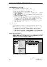
Page 38: ...ncel 1 Execute program scan s Figure 2 14 Executing Your Program for a Specific Number of Scans Displaying the Status of the Program in Ladder Logic As shown in Figure 2 15 the program editor of STEP 7 Micro WIN allows you to monitor the status of the online program The program must be displaying ladder logic This allows you to monitor the status of the instructions in the program as they are exec...

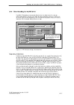
Page 39: ...ming any or all functions The objective for handling fatal errors is to bring the PDS 210 to a safe state from which the PDS 210 can respond to interrogations about the existing error conditions When a fatal error is detected by the PDS 210 the PDS 210 changes to the STOP mode turns on the System Fault LED and the STOP LED and turns off the outputs The PDS 210 remains in this condition until the f...

Page 40: ...RUN mode are reflected in special memory SM bits Your program can monitor and evaluate these bits Refer to Appendix B for more information about the SM bits used for reporting non fatal run time errors S Program compile errors The PDS 210 compiles the program as it downloads If the PDS 210 detects that the program violates a compilation rule the download is aborted and an error code is generated A...

Page 41: ...opment Station PDS 210 PC PPI Communications Cable Computer STEP 7 Micro WIN Figure 3 1 Requirements to Run the Sample Program Chapter Overview Section Description Page 3 1 Defining the Requirements for the Application Example 3 2 3 2 Designing the Control Logic 3 4 3 3 Putting the Control Logic into a Program 3 9 3 4 Creating a Project with STEP 7 Micro WIN 3 13 3 5 Creating a Symbol Table 3 14 3...

Page 42: ...n automatic dialing machine Figure 3 3 shows a wiring diagram for the home security application Creating Symbolic Names for the Elements of the Program Symbolic names help to document or define the specific memory locations or I O used by your program Table 3 1 lists the symbolic names used by the program for the sample application The sample program also uses SM0 5 to generate an on off blinking ...

Page 43: ...M Zone 1 Zone 2 Figure 3 2 Sample Application for a Home Security System Modem Dialer Relay Q0 0 Q0 2 I0 0 I0 1 I0 2 I0 3 1M A B C D E F Zone 1 Panic Alarm Arm Disarm System System LED High level Alarm Low level Alert Inputs Outputs H I J K L M Zone 2 Q0 1 2L Q0 3 1L Figure 3 3 Wiring Diagram for the Sample Home Security Application Getting Started with a Sample Program ...

Page 44: ...s If either zone I0 0 or I0 1 opens the program starts a notification sequence that turns on the low level alert buzzer Q0 2 and starts a timer This allows a reminder and time for the owner to disarm the system after returning home S Once the notification sequence has started the program has two possible actions If the system is disarmed by turning the key to the off or disarm position which turns...

Page 45: ...onds and if either Zone 1 or Zone 2 is open then start the alert timer and turn on the low level alert notification If not disarmed and the alert timer is 60 seconds then sound the alarm start the modem dialer and turn off the low level alert Turn on the alarm and start the modem dialer On and Off On On Off On On If disarmed then turn off the outputs and stop the alert timer Off Figure 3 4 Basic T...

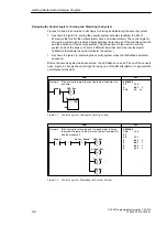
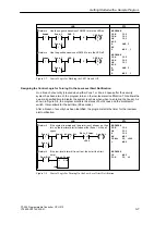
Page 46: ...As shown in Figure 3 6 disarming the security system stops the notification and alarm sequence Before the security system has been armed the LED flashes on and off if one of the zones is open Figure 3 7 shows the control logic for using one of the SM bits SM0 5 to generate the on off pulse for the LED LAD STL Network Armed NETWORK LD I0 2 S M0 0 1 TON T2 0 If the system is armed then set the lamp ...

Page 47: ...evel alert notification This allows the owner a specified time to disarm the system such as when when re entering the house As shown in Figure 3 8 the program monitors the states of both zones and the arm disarm switch It also allows for the exit time 90 seconds After a breach of security has been identified the program starts the timer for the low level alert notification NETWORK LDN I0 0 ON I0 1...

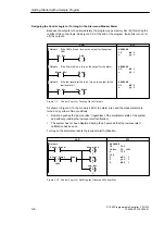
Page 48: ...he low level alert NETWORK LD M0 1 Q0 1 NETWORK LD M0 2 Q0 2 Figure 3 9 Control Logic for Turning On the Outputs As shown in Figure 3 10 the memory bits for the alarm siren and the modem dialer are turned on by either of two conditions S Someone pushes the panic button regardless of the arm disarm state of the system and without providing the low level alert notification S The system has not been ...

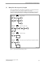
Page 49: ... the sample program This program includes the control logic from Section 3 2 The program ends with the End instruction Sound the alarm Evaluate the system status Start the Alert timer If the system is armed then set the lamp bit and start the exit timer T0 I 600 I0 3 I0 2 M0 1 S 1 Q0 3 S 1 M0 2 R I0 2 M0 2 S I0 0 I0 1 M0 1 TON IN PT T0 0 M0 2 Continued T2 I 900 TON IN PT T2 0 I0 2 M0 0 S 1 1 1 Net...

Page 50: ... 0 R 1 I0 2 I0 1 SM0 5 N I0 0 M0 0 S 1 I0 2 I0 1 SM0 5 P Use the positive transition to turn the LED off Use the negative transition to turn the LED on Reset everything if the system is disarmed I0 3 M0 0 R 1 I0 2 M0 1 R 1 M0 2 R 1 Q0 3 R 1 Network 5 Network 6 Network 7 Network 8 Network 9 Network 10 Network 11 P Figure 3 11 Home Security Program Example in Ladder continued Getting Started with a ...

Page 51: ...t the low level alert bit NETWORK 3 LD M0 2 TON T0 0 if the low level alert bit has been set then start the alert timer NETWORK 4 LD I0 2 S M0 0 1 TON T2 0 when the system is armed set the LED bit and start the exit timer NETWORK 5 LDN I0 2 EU AN I0 3 R M0 0 1 R M0 1 1 R M0 2 1 R Q0 3 1 if the system is not armed and the panic alarm is not on then reset LED bit reset High Level Alarm bit reset Low...

Page 52: ...tement List continued NETWORK 9 LD M0 1 Q0 1 if the high level alarm bit has been set turn on the high level alarm output NETWORK 10 LD M0 2 Q0 2 if the low level alert bit has been set turn on the low level alert output NETWORK 11 MEND end of the main program Getting Started with a Sample Program ...

Page 53: ...owin project1 prj 2 c microwin project2 prj 3 c microwin project3 prj Exit CPU Type Cancel OK Select or read the CPU type from your PLC if you would like the software to limit the available options to only those supported by a specific CPU Read CPU Type Communications PDS 210 CPU Type Figure 3 12 Creating a New Project and Selecting the CPU Type Project Edit View CPU Debug Tools Setup Window Help ...

Page 54: ...TER The focus moves to the cell in the Comment column Comments are optional but they are a useful way to document the elements in your program 3 Press ENTER to start the next symbol row and repeat these steps for each of the remaining symbol names and addresses 4 Use the menu command Project Save All to save your Symbol Table Symbol Name Address Comment Zone_1 Zone_2 Armed Panic_Alarm LED I0 0 I0 ...

Page 55: ...indicates that symbolic addressing is enabled Note Symbol names are case sensitive The name you enter must match exactly the uppercase and lowercase characters entered in the symbol table If there is any mismatch the cursor stays on the element and displays the Add Symbol dialog You can then add the new symbol to the Symbol Table or cancel and correct the entry Using the Ladder Editor to Enter the...

Page 56: ...e software accepts entry of either form 3 Press ENTER to confirm the first element The symbol name Panic_Alarm is displayed The ladder cursor moves to the second column position 4 Click the F8 toolbar button to insert a horizontal line You can also select Lines from the family listing and then select Horizontal from the instruction listing To change or replace one of the elements move the cursor t...

Page 57: ...efault value of 1 The CPU 210 allows only one point to be set or reset by any one Set or Reset instruction 4 Move the cursor to the position below the first contact Output Coils Set Network 1 F4 F5 F8 F7 F6 F10 F3 F2 Sound the alarm Panic_Alarm Reset Output Set Output Coils Set Network 1 F4 F5 F8 F7 F6 F10 F3 F2 Sound the alarm Panic_Alarm S 1 Q0 0 Enter the address M0 1 or Alarm_Bit Output Coils ...

Page 58: ... than or equal to 600 which equals 60 seconds 4 Click the F4 toolbar button to create a normally open contact Type Armed or I0 2 and press ENTER Contacts Integer Network 1 F4 F5 F8 F7 F6 F10 F3 F2 Sound the alarm Panic_Alarm Integer Normally Open Normally Closed Not Integer Positive Transition Negative Transition Integer Select Integer from the instruction listing Contacts Integer Network 1 F4 F5 ...

Page 59: ...e default value of 1 Lines Vertical Network 1 F4 F5 F8 F7 F6 F10 F3 F2 Sound the alarm Panic_Alarm S 1 Alarm_Bit I 600 Alert_Timer Armed Click the toolbar button to insert a vertical line Output Coils Set Network 1 F4 F5 F8 F7 F6 F10 F3 F2 Sound the alarm Panic_Alarm S 1 Alarm_Bit I 600 Alert_Timer Armed Copy the Set instruction by selecting the Copy command from the Edit menu Output Coils Set Net...

Page 60: ...ton to insert a vertical line Output Coils Reset Network 1 F4 F5 F8 F7 F6 F10 F3 F2 Panic_Alarm S 1 Alarm_Bit I 600 Alert_Timer Armed S 1 Modem Sound the alarm Integer Select Reset from the instruction listing Output Set Reset Output Coils Reset Network 1 F4 F5 F8 F7 F6 F10 F3 F2 Panic_Alarm S 1 Alarm_Bit I 600 Alert_Timer Armed S 1 Modem Sound the alarm Integer Enter the address M0 2 or Low_Bit a...

Page 61: ...n in the sample program you will get a Compile Successful message that also includes information on the number of networks and the amount of memory used by the program Otherwise the Compile message will indicate which networks contain errors Saving the Sample Program Saving the project saves all the components of your sample project You save your project by selecting the menu command Project Save ...

Page 62: ...following Zone_1 Press ENTER to confirm your entry This element type can only be displayed in bit format either 1 or 0 so you cannot change the format type 2 Select the next row and repeat these steps for each of the remaining elements as shown in Figure 3 21 You can use the menu command Edit Insert Row s or the INSERT or INS key to insert a blank row above the row containing the cursor Timers and...

Page 63: ...t ensure that all memory locations I O addresses and instructions used by your program are valid for the PDS 210 and CPU 210 Using the Ladder Editor to Monitor the Status of the Program Ladder status shows the current state of events in your program Reopen the Ladder Editor window if necessary and select the menu command Debug Ladder Status On If you have an input simulator connected to the input ...

Page 64: ...lements in your program click the Single Read button or the Continuous Read button in the Status Chart window S To stop the reading of status click the Stop button in the Status Chart window Project Edit View CPU Debug Tools Setup Window Help STEP 7 Micro WIN c microwin house prj Status Chart Address Format Change Value To Current PLC Value Bit Bit Bit Bit Bit Zone_1 Bit Bit Bit 2 0 2 0 2 0 2 0 Zo...

Page 65: ...emory MW3 Blink_Pattern Stores the pattern for flashing the LED on and off Timers T1 Blink_Timer Increments the step counter Creating the Blink Patterns for the LED The program uses different bit patterns as the basis for the logic that turns the LED on and off Based on the condition the program loads a value into the word that stores the blink pattern Figure 3 24 shows the networks that move the ...

Page 66: ...er Zone 1 or Zone 2 becomes open I0 2 I0 0 I0 1 Figure 3 25 Control Logic for Starting the Light Blink Timer Figure 3 26 shows the control logic for incrementing the count for the number of times that the light blink logic has been performed LAD STL Network 10 NETWORK LDW T1 4 M0 7 R M0 0 1 INCW MW1 If the light blink timer is less than or equal to 400 ms then set the light blink timer bit reset t...

Page 67: ... on set the LED bit if the system is not armed M4 0 I0 2 M0 0 S 1 MW1 I 1 M4 1 MW1 I 2 M4 2 MW1 I 3 M4 5 MW1 I 6 M4 6 MW1 I 7 M4 7 MW1 I 8 Figure 3 27 Control Logic for Controlling the Blink Pattern LAD STL Network 12 NETWORK LDW MW1 10 LD I0 0 A I0 1 OLD MOVW 0 MW1 If the step counter equals 10 and both Zone 1 and Zone 2 are closed then reset the step counter to 0 MW1 I 10 MOV_W EN IN OUT 0 MW1 I...

Page 68: ...3 28 S7 200 Programmable Controller CPU 210 C79000 G7076 C235 01 Getting Started with a Sample Program ...

Page 69: ...ic operational features Chapter Overview Section Description Page 4 1 Guidelines for Designing a Micro PLC System 4 2 4 2 Concepts for Creating a Program 4 4 4 3 Understanding the Scan Cycle of the CPU 210 4 6 4 4 Understanding the Programming Languages 4 9 4 5 Understanding the Addresses of the Memory Areas 4 11 4 6 Sample Program Using an Interrupt Routine 4 14 4 7 Using the Analog Adjustment Po...

Page 70: ...s optional Design the hard wired safety circuits Figure 4 1 Basic Steps for Planning a PLC System Partitioning Your Process or Machine Divide your process or machine into sections that have a level of independence from each other These partitions will determine the boundaries between controllers and will influence the functional description specifications and the assignment of resources Creating t...

Page 71: ...operation independent of the CPU S Provide appropriate status information from the independent circuits to the CPU 210 so that the program and any operator interfaces have necessary information S Identify any other safety related requirements for safe operation of the process Specifying the Operator Stations Based on the requirements of the functional specifications create drawings of the operator...

Page 72: ...he physical output Each memory area is assigned a mnemonic identifier such as I for input that is used for accessing the data stored in that area of memory S Drain Solenoid Operator Station Input Area CPU 210 Input Output Opn_Drn_PB Drain_Sol Cls_Drn_PB A_Mtr_Fbk Drain_Sol E_Stop_On Figure 4 2 Relating the Program to Inputs and Outputs Accessing Data in the Memory Areas All of the memory areas of ...

Page 73: ...se instructions on a specific hardware event the rising edge when I0 0 turns on Place the interrupt routine after the end of the main program following the Unconditional End MEND instruction Use a Return From Interrupt RETI instruction to terminate the interrupt routine Section 4 6 provides an example of a program using an interrupt routine The interrupt routine is not executed as part of the norm...

Page 74: ...talled the CPU 210 restores the current values for the four counters 2 The CPU 210 filters the inputs and updates the value of the analog adjustment potentiometer stored in SMW2 This delays the scan by approximately 15 ms 3 The CPU 210 executes the user program As the program writes values to the outputs the CPU 210 immediately updates the outputs 4 The CPU 210 updates the time base for the 100 ms...

Page 75: ...ates the timers before executing the program 4 The PDS 210 executes the user program As the program writes values to the outputs the PDS 210 immediately updates the outputs 5 The PDS 210 processes any communication requests from STEP 7 Micro WIN The interrupt routine is not executed as part of the normal scan cycle but is executed when the interrupt event occurs which may be at any point in the sc...

Page 76: ...0 updates the time base for the 100 ms timers 4 The PDS 210 executes the user program As the program writes values to the outputs the PDS 210 immediately updates the outputs 5 The PDS 210 processes any communication requests from STEP 7 Micro WIN 6 If you specified more than 1 scan the PDS 210 starts the next scan starting with Step 2 7 After the specified number of scans have been run the PDS 210...

Page 77: ...ments of Ladder When you write a program in ladder you create and arrange the graphical components to form a network of logic As shown in Figure 4 7 the following types of elements are available for creating your program S Contacts each of these elements represents a switch through which power can flow when a switch is closed S Coils each of these elements represents a relay that is energized by p...

Page 78: ...o bits of the stack are combined the stack is popped reduced by one bit While most STL instructions only read the values in the logic stack many STL instructions also modify the values stored in the logic stack Figure 4 9 shows three examples of how three instructions use the logic stack S0 S1 S2 S3 S4 S5 S6 S7 Stack 0 First stack level or top of the stack Stack 1 Second stack level Stack 2 Third ...

Page 79: ...bit units allows the following ranges of integer values S Unsigned Integer 0 to 65 535 decimal 0 to FFFF hexadecimal S Signed Integer 32 768 to 32 767 decimal 8000 to 7FFF hexadecimal Using the Memory Address to Access Data To access a bit in a memory area you specify the address which includes the memory area identifier the byte address and the bit number Figure 4 11 shows an example of addressin...

Page 80: ...0 bit address I0 1 Addressing the Outputs Q When the control logic of the program turns an output coil on the CPU immediately turns that output on Format Bit Q0 bit address Q0 0 Addressing the Bit Memory M Area You can use the internal memory bits M memory as control relays to store the intermediate status of an operation or other control information Format Bit M byte address bit address M2 7 Word...

Page 81: ...ramming instructions for the CPU 210 allow you to use constant values These constants can only be word length signed integers The CPU stores all constants as binary numbers which can then be represented in decimal hexadecimal or ASCII formats Decimal Format decimal value Hexadecimal Format 16 hexadecimal value ASCII Format ASCII text The CPU 210 does not support data typing or data checking such a...

Page 82: ...counts the pulses that it receives over a period of time 5 seconds Based on the count which relates to the temperature the CPU 210 turns a digital output on or off 3 The power contactor turns the resistance heater on or off based on the state of the output of the CPU 210 Figure 4 14 shows a sample program for this application example This example counts up to 3 kHz Pulse train waveform up to 3 kHz...

Page 83: ...een turned off Network 3 After 5 seconds turn off the timer and disable the interrupt routine Network 4 While the timer is executing jump over the logic that tests the number of counts Network 5 If timer has stopped turn on Q0 0 if the number of counts is less than or equal to 15200 T0 I 50 DISI Network 4 JMP 0 M0 0 M0 0 R 1 M0 0 I0 1 MW2 I 15200 Q0 0 Network 7 Network 8 INT 0 Network 6 LBL 0 Netw...

Page 84: ...Adjustment Potentiometer SMW2 stores the digital value that represents the position of the analog adjustment potentiometer The CPU 210 samples the analog adjustment potentiometer at least three times a second and has a range from 0 to 255 The new value of the analog adjustment potentiometer is written to SMW2 at the beginning of the next scan The analog adjustment potentiometer on the PDS 210 has ...

Page 85: ...ditional executes according to condition of preceding logic Unconditional executes without preceding logic Chapter Overview Section Description Page 5 1 Valid Ranges for the CPU 210 and PDS 210 5 2 5 2 Contact Instructions 5 3 5 3 Output Instructions 5 5 5 4 Timer Instructions 5 6 5 5 Counter Instructions 5 8 5 6 Increment and Decrement Instructions 5 9 5 7 Move Instruction 5 10 5 8 Program Contro...

Page 86: ... valid ranges of the operands used to access data in the different memory areas These ranges vary according to the size of the data being accessed Table 5 1 Operand Ranges Access Method CPU 210 and PDS 210 Bit Access Byte bit I 0 0 to 0 3 Q 0 0 to 0 3 M 0 0 to 5 7 SM 0 0 to 1 7 Word Access T 0 to 3 C 0 to 3 MW 0 to 4 SMW 0 to 2 Constant Instruction Set ...

Page 87: ... reach the Not contact it sources power flow In STL the Not instruction changes the value on the top of the stack from 0 to 1 or from 1 to 0 Operands none Positive Negative Transition The Positive Transition contact allows power to flow for one scan for each off to on transition In STL the Positive Transition contact is represented by the Edge Up instruction Upon detection of a 0 to 1 transition i...

Page 88: ...son by using the Not instruction with the or compare instruction The following sequence is equivalent to a comparison of MW0 to 50 LDW MW0 50 NOT Contact Examples NETWORK 1 LD I0 0 A I0 1 Q0 0 NETWORK 2 LD I0 0 NOT Q0 1 NETWORK 3 LD I0 1 ED Q0 2 NETWORK 4 LDW MW0 MW2 Q0 3 Network 1 Q0 0 LAD STL I0 0 I0 1 Network 2 Q0 1 I0 0 NOT Network 3 Q0 2 I0 1 N Network 4 Q0 3 MW0 MW2 I Timing Diagram I0 0 I0 ...

Page 89: ...specified parameter n Operands n Q M Set Reset When the Set and Reset instructions are executed the point specified by S_BIT is set turned on or reset turned off Operands S_BIT Q M Output Example NETWORK LD I0 0 Q0 0 S Q0 1 1 R Q0 2 1 Network 1 Q0 0 LAD STL I0 0 S Q0 1 R Q0 2 Timing Diagram I0 0 Q0 0 Q0 1 Q0 2 1 1 Figure 5 2 Example of Output Instructions Instruction Set L A D S T L n n L A D S T ...

Page 90: ...cumulated number of 100 ms intervals since the beginning of the previous scan to the current value for that timer when the timer instruction is executed The update of the timers is not automatic since the current value of a timer is updated only if the timer instruction is executed Consequently if a timer is enabled but the timer instruction is not executed each scan the current value for that tim...

Page 91: ...t T1 3 Q0 2 TON IN PT T1 Q0 2 T1 I 3 0 I0 2 T1 3 Figure 5 3 Example of the Timer Instruction TON IN PT T0 M0 0 T0 I 30 0 M0 0 LAD STL Network LDN M0 0 Enable disable the timer TON T0 0 Select timer T0 Network LDW T0 30 Every 3 seconds M0 0 Turn on M0 0 which then disables the timer Figure 5 4 Example of an Automatically Retriggered One Shot Timer Instruction Set ...

Page 92: ...ent value Since there is one current value for each counter do not assign the same number to more than one counter Up Down Counter The Up Down Counter instruction counts up on rising edges of the Count Up CU input It counts down on the rising edges of the Count Down CD input The counter resets when the Reset R input turns on In STL the Reset input is the top of the stack value the Count Down input...

Page 93: ...en programming in ladder if you specify the address for IN to be the same address as OUT you can reduce the amount of memory required These instructions affect the following Special Memory bits SM1 0 zero SM1 1 overflow SM1 2 negative Increment Decrement Example LAD STL Network LD I0 0 INCW MW0 DECW MW2 INC_W EN IN MW0 OUT MW0 DEC_W EN IN MW2 OUT MW2 125 increment MW0 MW0 5000 4999 Application dec...

Page 94: ...put word IN to the output word OUT The input word is not altered by the move Operands IN T C MW SMW Constant OUT T C MW Move Examples LAD STL Network LD I0 1 MOVW SMW2 MW2 I0 1 MOV_W EN OUT MW2 SMW2 IN Application 127 SMW2 MW2 move 127 Move Figure 5 7 Example of Move Instruction Instruction Set L A D S T L MOVW IN OUT MOV_W EN IN OUT ...

Page 95: ... None Considerations for Using the WDR Instruction to Reset the Watchdog Timer You should use the Watchdog Reset instruction carefully If you use looping instructions to either prevent scan completion or to excessively delay the completion of the scan the following processes are inhibited until the scan cycle is terminated S Inputs will not update S Special memory SM will not update SM0 SMW2 S Tim...

Page 96: ... Operands n 0 to 63 Both the Jump and corresponding Label must be in the main program or in the interrupt routine You cannot jump from the main program to a label in the interrupt routine Likewise you cannot jump from the interrupt routine to a label outside the interrupt routine Jump to Label Example LAD SM0 1 If this is not the first scan jump to LBL 4 Network LDN SM0 1 JMP 4 Network LBL 4 You c...

Page 97: ...tack After the OLD executes the stack depth is one less Operands none Figure 5 10 illustrates the operation of the And Load and Or Load instructions S0 iv2 iv3 iv4 iv5 iv6 iv7 x ALD AND the top two stack values iv0 iv1 iv2 iv3 iv4 iv5 iv6 iv7 Before After S0 iv0 iv1 OLD OR the top two stack values S0 iv0 iv1 S0 iv2 iv3 iv4 iv5 iv6 iv7 x iv0 iv1 iv2 iv3 iv4 iv5 iv6 iv7 Before After Note x means the...

Page 98: ...al Return from Interrupt coil must be used to terminate the interrupt routine Operands n 0 You can identify the interrupt routine by the interrupt routine label that marks the entry point into the routine The routine consists of all your instructions between the interrupt label and the unconditional return from interrupt instruction The interrupt routine executes in response to the rising edge of ...

Page 99: ...in program Problems with the consistency of shared data can result due to the actions of the interrupt routine when the execution of instructions in your main program is interrupted by an interrupt event There are a number of programming techniques you can use to ensure that data is correctly shared between your main program and interrupt routine These techniques either restrict the way access is ...

Page 100: ...e timer on after it has been turned off Network 3 After 5 seconds turn off the timer and disable the interrupt routine Network 4 While the timer is executing jump over the logic that tests the number of counts Network 5 If timer has stopped turn on Q0 0 if the number of counts is between 14550 and 15200 T0 I 50 DISI Network 4 JMP 0 M0 0 M0 0 R 1 M0 0 MW2 I 14550 I0 1 MW2 I 15200 Q0 0 Network 7 Net...

Page 101: ...ons A 2 A 2 CPU 210 DC Power Supply 24 VDC Inputs 24 VDC Outputs A 4 A 3 CPU 210 AC Power Supply 24 VDC Inputs Relay Outputs A 6 A 4 CPU 210 AC Power Supply AC Inputs Relay Outputs A 8 A 5 PDS 210 AC Power Supply DC Inputs Relay Outputs A 10 A 6 Memory Cartridge 8K x 8 A 12 A 7 Memory Cartridge 16K x 8 A 13 A 8 PC PPI Cable A 14 A 9 DC Input Simulator A 15 A ...

Page 102: ...ndustrial environment Electromagnetic immunity standards EN 50082 2 industrial environment Technical Specifications The S7 200 CPUs and all S7 200 expansion modules conform to the technical specifications listed in Table A 1 Table A 1 Technical Specifications for the S7 200 Family Environmental Conditions Transport and Storage IEC 68 2 2 Test Bb Dry heat IEC 68 2 1 Test Ab Cold 40 C to 70 C IEC 68...

Page 103: ... 30 MHz to 230 kHz 230 MHz to 1 GHz 30 dB µV m Quasi peak measured at 30 meters 37 dB µV m Quasi peak measured at 30 meters EN 55011 Class B Group 1 conducted4 0 15 to 0 5 MHz 0 5 to 5 MHz 5 to 30 MHz 66 dB µV Quasi peak decreasing with log frequency to 56 dB µV 56 dB µV Average decreasing with log frequency to 46 dB µV 56 dB µV Quasi peak 46 dB µV Average 60 dB µV Quasi peak 50 dB µV Average EN 5...

Page 104: ...epetitive per common 2A L R 10 ms 1A L R 100 ms 1 W energy dissipation 1 2 Li2 x switch rate t 1 W Leakage Current 100 µA Switching Delay 25 µs on 120 µs off Surge Current 4 A 100 ms Voltage Drop 1 8 V maximum at maximum current Optical Isolation 500 VAC 1 minute Short Circuit Protection None Input Points Input Type IEC 1131 2 Sink Source IEC 1131 Type 1 in Sink mode ON State Range 15 30 VDC 4 mA ...

Page 105: ...ms 470 ohms Power Supply Note Actual component values may vary DC OUTPUTS 36V 36V M L 0 0 0 1 0 2 0 3 1M 0 0 0 1 0 2 0 3 M L DC INPUTS 24 V DC OUT 24 VDC Power for Input Sensors Analog Adjustment Potentiometer Location for the Memory Cartridge Figure A 1 Connector Terminal Identification for CPU 210 DC DC DC CPU 210 Data Sheets ...

Page 106: ...s maximum Lifetime 10 000 000 Mechanical 100 000 with Rated Load Contact Resistance 200 mW maximum new Isolation coil to contact contact to contact 1500 VAC 1 minute 1000 VAC 1 minute Short Circuit Protection None Input Points Input Type IEC 1131 2 Sink Source IEC 1131 Type 1 in Sink mode ON State Range 15 35 VDC 4 mA minimum 35 VDC 500 ms surge ON State Nominal 24 VDC 7 mA OFF State Maximum 5 VDC...

Page 107: ...upply Note Actual component values may vary OUTPUTS 1L 0 0 0 1 2L 0 2 0 3 RELAY N L1 85 264 VAC 1M 0 0 0 1 0 2 0 3 DC INPUTS 24 VDC Power for Input Sensors 24 V DC OUT M L N L N L Analog Adjustment Potentiometer Location for the Memory Cartridge Figure A 2 Connector Terminal Identification for CPU 210 AC DC Relay CPU 210 Data Sheets ...

Page 108: ...nt Surge 7 A with contacts closed Isolation Resistance 100 MW minimum new Switching Delay 10 ms maximum Lifetime 10 000 000 Mechanical 100 000 with Rated Load Contact Resistance 200 mW maximum new Isolation coil to contact contact to contact 1500 VAC 1 minute 1000 VAC 1 minute Short Circuit Protection None Input Points Input Type IEC 1131 2 Type 1 Sinking ON State Range 164 to 265 VAC 47 to 63 Hz ...

Page 109: ...ay vary Inputs 164 to 265 VAC N 0 0 0 1 0 2 0 3 Outputs 30 VDC 250 VAC Power Supply 1L 0 0 0 1 2L 0 2 0 3 RELAY OUTPUTS N L1 85 264 VAC AC INPUTS 0 1 F N L N L Analog Adjustment Potentiometer Location for the Memory Cartridge Figure A 3 Connector Terminal Identification for CPU 210 AC AC Relay CPU 210 Data Sheets ...

Page 110: ...um new Switching Delay 10 ms maximum Lifetime 10 000 000 Mechanical 100 000 with Rated Load Contact Resistance 200 mW maximum new Isolation coil to contact contact to contact 1500 VAC 1 minute 1000 VAC 1 minute Short Circuit Protection None Input Points Input Type IEC 1131 2 Type 1 Sinking ON State Range 15 30 VDC 4 mA minimum 35 VDC 500 ms surge ON State Nominal 24 VDC 7 mA OFF State Maximum 5 VD...

Page 111: ...L terminal N L1 85 264 VAC Outputs 30 VDC 250 VAC N L Power Supply 1L 0 0 0 1 0 2 0 3 RELAY OUTPUTS M L DC SENSOR SUPPLY Inputs 15 to 30 VDC 24 VDC Power for Input Sensors 1M 0 0 0 1 0 2 0 3 DC 24V INPUTS Location of the Analog Adjustment Potentiometer and the Memory Cartridge Figure A 4 Connector Terminal Identification for PDS 210 AC DC Relay CPU 210 Data Sheets ...

Page 112: ...x D 28 x 10 x 16 mm 1 1 x 0 4 x 0 6 in Weight 3 6 g 0 01 lbs Power Dissipation 0 5 mW Memory Type EEPROM User Storage 8 192 bytes Standards Compliance UL 508 CSA C22 2 142 FM Class I Division 2 VDE 0160 compliant CE compliant Memory Cartridge Dimensions 28 5 mm 1 12 in 16 5 mm 0 65 in 11 mm 0 42 in Figure A 5 Memory Cartridge Dimensions 8K x 8 CPU 210 Data Sheets ...

Page 113: ... D 28 x 10 x 16 mm 1 1 x 0 4 x 0 6 in Weight 3 6 g 0 01 lbs Power Dissipation 0 5 mW Memory Type EEPROM User Storage 16 384 Bytes Standards Compliance UL 508 CSA C22 2 142 FM Class I Division 2 VDE 0160 compliant CE compliant Memory Cartridge Dimensions 28 5 mm 1 12 in 16 5 mm 0 65 in 11 mm 0 42 in Figure A 6 Memory Cartridge Dimensions 16K x 8 CPU 210 Data Sheets ...

Page 114: ...ted by dip switch Switch 38 4 k 0000 19 2 k 0010 9 6 k 0100 2 4 k 1000 1 2 k 1010 600 1100 Standards Compliance UL 508 CSA C22 2 142 FM Class I Division 2 VDE 0160 compliant CE compliant Table A 2 PC PPI Cable Pin Out RS 232 Pin Function Computer End RS 485 Pin Function PDS 210 End 2 Received Data PC listens 8 Signal A 3 Transmitted Data PC sends 3 Signal B 5 Signal Common 7 24 V 2 24 V Return PLC...

Page 115: ... 0XA0 General Features Physical Size L x W x D 91 x 36 x 22 mm 3 6 x 1 4 x 0 85 in Weight 0 03 kg 0 06 lb Points 14 Note The PDS 210 supports only 4 of the 14 simulator points 23 mm 0 9 in 1 0 0 0 0 1 0 2 0 3 M L DC SENSOR SUPPLY 1M DC 24V INPUTS Figure A 8 Installation of the DC Input Simulator CPU 210 Data Sheets ...

Page 116: ...A 16 S7 200 Programmable Controller CPU 210 C79000 G7076 C235 01 CPU 210 Data Sheets ...

Page 117: ...s off for 30 seconds and on for 30 seconds for a cycle time of 1 minute It provides an easy to use delay or a 1 minute clock pulse SM0 5 This bit provides a clock pulse that is off for 0 5 seconds and then on for 0 5 seconds for a cycle time of 1 second It provides either an easy to use delay or a 1 second clock pulse SM0 6 This bit is a scan clock which is off for one scan and then on for the nex...

Page 118: ...emory Word SMW2 SM Word Description SMW2 This word stores the value entered with the analog adjustment potentiometer This value is updated once per scan SMW4 through SMW20 Reserved SMW4 through SMW20 are reserved for future use SMW22 to SMW26 Scan Times only for the PDS 210 SMW22 to SMW26 are available only through communications with the PDS 210 As described in Table B 3 SMW22 SMW24 and SMW26 pro...

Page 119: ... 0089 Missing RETI or instruction not allowed in an interrupt routine add RETI to the end of the interrupt routine or remove incorrect instruction 008C Duplicate Label LBL or INT rename one of the labels 008D Illegal Label LBL or INT ensure the number of labels allowed was not exceeded 0090 Illegal parameter verify the allowed parameters for the instruction 0091 Range error with address informatio...

Page 120: ...ity of the error a fatal error can render the CPU 210 incapable of performing any or all functions When the CPU 210 detects a fatal error it turns on the fault indicator and clears the outputs It remains in this condition until the error has been corrected and the power has been cycled The CPU 210 can detect the following error conditions S Error during the power up diagnostics these errors can in...

Page 121: ...ant to import Double click to display the contents in the list box on the left as shown in Figure D 1 4 Select the program in the list box or type the program name in the File Name field 5 Click the OK button The Micro DOS program and associated files open as an untitled project Project New Ctrl N Open Ctrl O Close Save All Ctrl S Save As Import Export Upload Ctrl U Download Ctrl D Print Ctrl P Pr...

Page 122: ...ame name as the Micro DOS program is converted to a Micro WIN status chart For example if you have a program named TEST VPU that has status charts TEST CH2 and TEST2 CH2 the status chart named TEST is imported but not the status chart named TEST2 S The network address password privilege level output table and retentive ranges are set based upon the Micro DOS files You can find these parameters wit...

Page 123: ...re is also an additional overhead that is associated with the system clock add 60 s for every 1 ms counted by the system clock Table E 1 Execution Times for the STL Instructions in µs Instruction Description On µs Off µs Output valid for Q M 120 120 A And valid for I M SM 110 110 ALD And Load 60 60 AN And Not valid for I M SM 80 80 AW And Word if less than or equal 300 300 AW And Word if equal 300...

Page 124: ...0 MEND Main Program End 50 Not applicable MOVW Move Word 210 170 NOT Not 60 60 O Or valid for I M SM 110 110 OLD Or Load 60 60 ON Or Not valid for I M SM 110 110 OW Or Word is less than or equal 300 300 OW Or Word if equal 300 300 OW Or Word if greater than or equal 300 300 R Reset 120 70 RETI Return from Interrupt Add 100 µs if the interrupt routine uses any of the following instructions S MOVW S...

Page 125: ...mber Memory Cartridge 8K x 8 6ES7 291 8GC00 0XA0 Memory Cartridge 16K x 8 6ES7 291 8GD00 0XA0 PC PPI Cable 6ES7 901 3BF00 0XA0 DC Input Simulator 6ES7 274 1XH00 0XA0 10 Position Fan Out Connector package of 10 connectors 6ES7 290 2AA00 0XA0 Programming Software Order Number STEP 7 Micro WIN Individual License 6ES7 810 2AA00 0YX0 STEP 7 Micro WIN Copy License 6ES7 810 2AA00 0YX1 STEP 7 Micro WIN Up...

Page 126: ...F 2 S7 200 Programmable Controller CPU 210 C79000 G7076 C235 01 CPU 210 Order Numbers ...

Page 127: ...LD instruction 5 13 effect on the logic stack 5 13 And Not AN instruction 5 3 Area identifier with device number accessing timers and counters 4 12 B Baud rate 2 3 bit memory See special memory SM bits Bit memory M 4 11 addressing 4 12 Bit byte addressing 4 11 Boxes represented in ladder 4 9 C Cables baud rate 2 3 order number F 1 pin assignment A 14 specifications PC PPI A 14 Case sensitive symbo...

Page 128: ... 210 2 11 Counter instructions 5 8 accessing the current value 4 13 addressing 4 13 current value 4 13 5 8 current values saved in the CPU 210 2 12 device number 4 12 example 5 8 up down counter 5 8 CPU 210 agency approvals A 2 analog adjustment location of the potentiometer 4 16 value stored in special memory SM B 2 basic operation 4 4 compile rule violations C 1 current values for counters saved...

Page 129: ...1 5 DIN rail dimensions 1 5 installing on a 1 6 using DIN rail stops 1 6 Disable Interrupt DISI instruction 5 14 5 17 disabling and enabling interrupts 5 14 Displaying status in ladder 2 16 Downloading a program CPU 210 2 11 PDS 210 2 10 2 12 sample program 3 23 Duplicate symbol names 2 13 E ED Negative Transition instruction 5 3 Editing a cell in a Status Chart 2 15 Editing a cell in the Symbol T...

Page 130: ...rst scan bit B 1 G Grounding and isolation wiring guidelines 1 9 Guidelines AC installation 1 10 case sensitive symbols 2 13 creating a program with STL 2 8 DC installation 1 10 designing a PLC system 4 2 4 3 entering symbolic addresses 2 13 grounding and isolation 1 9 number of characters per symbol 2 13 number of symbols allowed 2 13 overlapping memory addresses in symbol names 2 13 suppression ...

Page 131: ...ic Stack 5 13 Move Word MOVW 5 10 Negative Transition ED 5 3 Normally Open Normally Closed contact 5 3 NOT 5 3 On Delay Timer 5 6 Or O Or Not ON 5 3 effect on the logic stack 4 10 5 3 Or Load OLD 5 13 effect on logic stack 5 13 Outputs 5 5 Positive Transition EU 5 3 Program Control 5 11 5 12 Reset R 5 5 Return from Interrupt RETI 4 5 5 14 5 17 Set S 5 5 standard contacts 5 3 Timer 5 6 5 7 Uncondit...

Page 132: ...tion of the analog adjustment potentiometer 4 16 Logic stack 4 10 affected by the interrupt routine 5 15 effect of Or O And A Load LD 4 10 effect of Or Load OLD And Load ALD 5 13 Logic Stack instructions 5 13 And Load ALD 5 13 effect on logic stack 5 13 example 5 13 5 15 operation 5 13 Or Load OLD 5 13 effect on logic stack 5 13 M Main Program End MEND instruction 4 5 5 11 Main program segment 4 5...

Page 133: ...l instruction 5 5 represented in ladder 4 9 Output instructions 5 5 coil 5 5 example 5 5 represented in ladder 4 9 Reset R 5 5 Set S 5 5 Outputs addressing 4 12 basic operation 4 4 represented in ladder 4 9 writing to 4 6 4 9 Overview CPU 210 1 1 1 4 PDS 210 1 1 1 4 P Panel box See also Enclosure installing in a 1 7 Paste copy and cut in a Status Chart 2 15 in a Symbol Table 2 14 PC PPI cable baud...

Page 134: ... word 5 9 interrupt routine 4 14 4 16 5 16 jump to label 5 12 logic stack instructions 5 13 main program end 5 12 move word 5 10 output instructions 5 5 timer 5 7 watchdog reset 5 12 executing 4 6 4 9 guidelines and limitations for converting files D 2 high speed counter example 4 14 4 16 5 16 importing files from STEP 7 Micro DOS D 1 languages 4 9 4 11 monitoring 2 16 networks 4 9 sample program ...

Page 135: ...ial memory SM B 2 Screw size for installation 1 6 Set S instruction 5 5 Setting the baud rate 2 3 Setting up communication parameters 2 4 selecting preferences in STEP 7 Micro WIN 2 5 Single read Status Chart option 2 15 See also Continuous read Status Chart Write Single phase wiring guidelines 1 10 SMW0 status bits B 1 SMW2 analog adjustment current value B 2 SMW22 to SMW26 scan times B 2 Special...

Page 136: ...ample program 3 1 3 25 entering instructions in the program 3 15 3 20 equipment requirements 2 1 installing 2 2 Ladder Editor 2 7 Ladder editor 2 16 online help 2 1 program examples contact instructions 5 4 counter 5 8 End MEND 5 12 high speed counter 4 14 4 16 5 16 increment decrement word 5 9 interrupt 4 14 4 16 5 16 jump to label 5 12 logic stack ALD and OLD 5 13 move word 5 10 output instructi...

Page 137: ...ory cartridge 2 12 STEP 7 Micro WIN installation 2 2 U Unconditional End MEND instruction 4 5 5 11 Up Down Counter CTUD instruction 5 8 User manual order number F 1 Using the Ladder Editor 3 15 3 20 V Valid ranges for CPU 210 1 3 4 11 4 13 5 2 W Watchdog Reset WDR instruction 5 11 5 13 considerations 5 11 Windows 3 1 installing STEP 7 Micro WIN 2 2 Windows 95 installing STEP 7 Micro WIN 2 2 Wiring...

Page 138: ...Index 12 S7 200 Programmable Controller CPU 210 C79000 G7076 C235 01 Index ...

Page 139: ...al Plastic Pulp and Paper Textiles Transportation Other _ _ _ _ _ _ _ _ _ _ _ From Your Name _ _ _ _ _ _ _ _ _ _ _ _ _ _ _ _ _ _ _ _ _ _ _ _ _ _ _ _ _ Your Title _ _ _ _ _ _ _ _ _ _ _ _ _ _ _ _ _ _ _ _ _ _ _ _ _ _ _ _ _ Company Name _ _ _ _ _ _ _ _ _ _ _ _ _ _ _ _ _ _ _ _ _ _ _ _ _ _ Street _ _ _ _ _ _ _ _ _ _ _ _ _ _ _ _ _ _ _ _ _ _ _ _ _ _ City Zip Code_ _ _ _ _ _ _ _ _ _ _ _ _ _ _ _ _ _ _ _ _ _...

Page 140: ..._ _ _ _ _ _ _ _ _ _ _ _ _ _ _ _ _ _ _ _ _ _ _ _ _ _ _ _ _ _ _ _ _ _ _ _ _ _ _ _ _ _ _ _ _ _ _ _ _ _ _ _ _ _ _ _ _ _ _ _ _ _ _ _ _ _ _ _ _ _ _ _ _ Remarks Form Your comments and recommendations will help us to improve the quality and usefulness of our publications Please take the first available opportunity to fill out this questionnaire and return it to Siemens Please give each of the following qu...

Reviews: